Lab 5 - EE 421L Fall 2020
For our Pre-lab work, we should go through the tutorial 3, which it explains how to draw the schmatic, symbol and layout of a CMOS inverter.
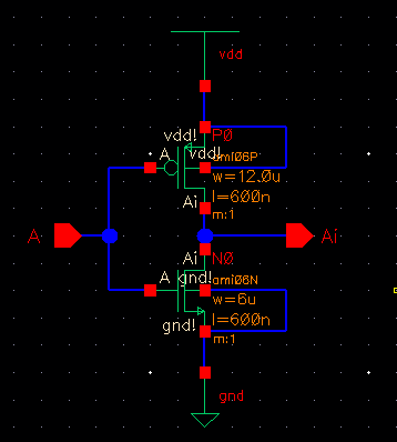
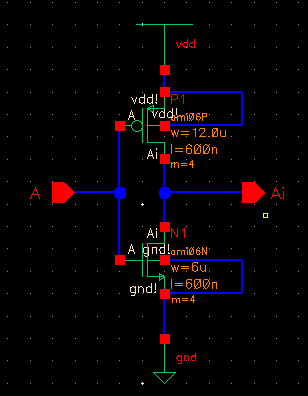
The schematic of the inverter is as following, it was using a 12u/0.6u PMOS and a 6u/0.6u NMOS.
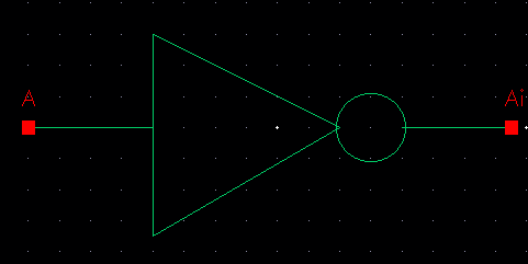
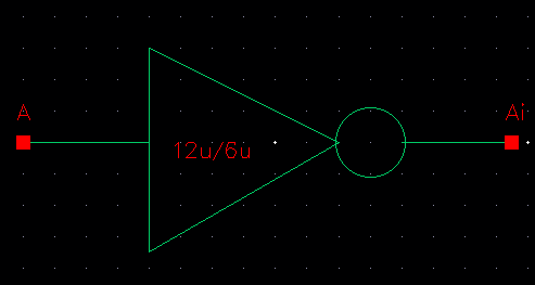
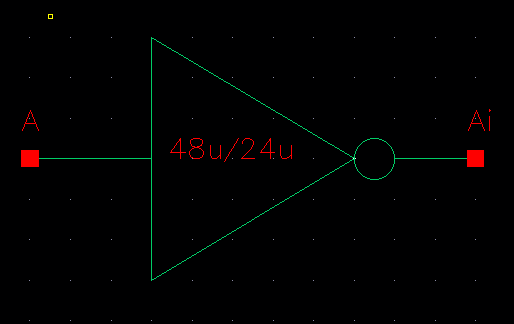
The symbol of the inverter:
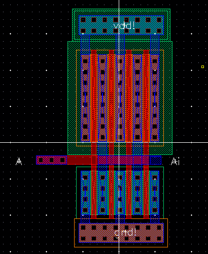
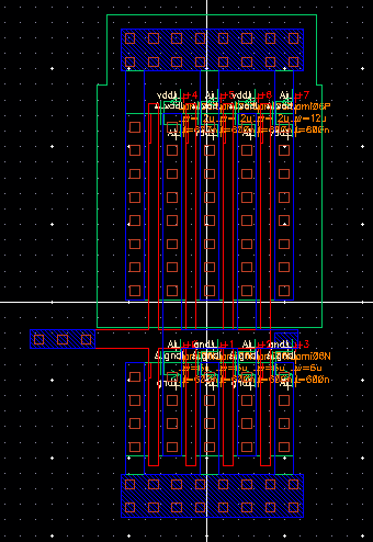
The layout view and the extracted view of the inverter:
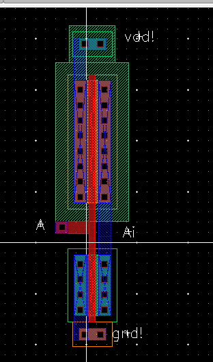

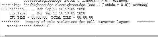
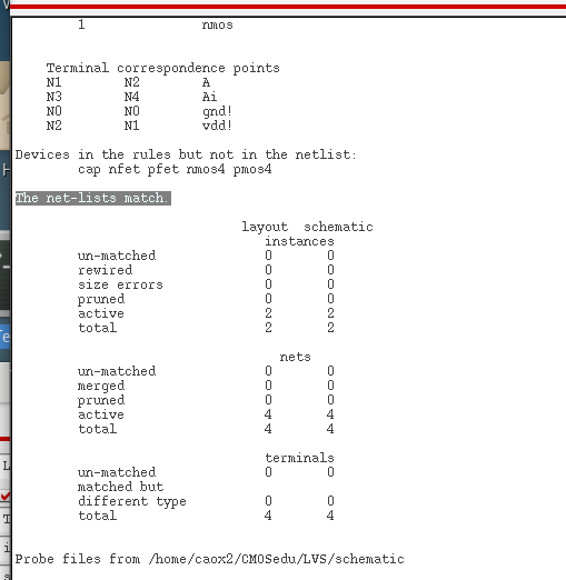
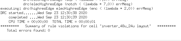
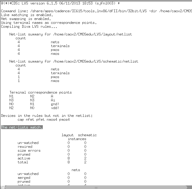
it passes the DRC and the LVS verification.
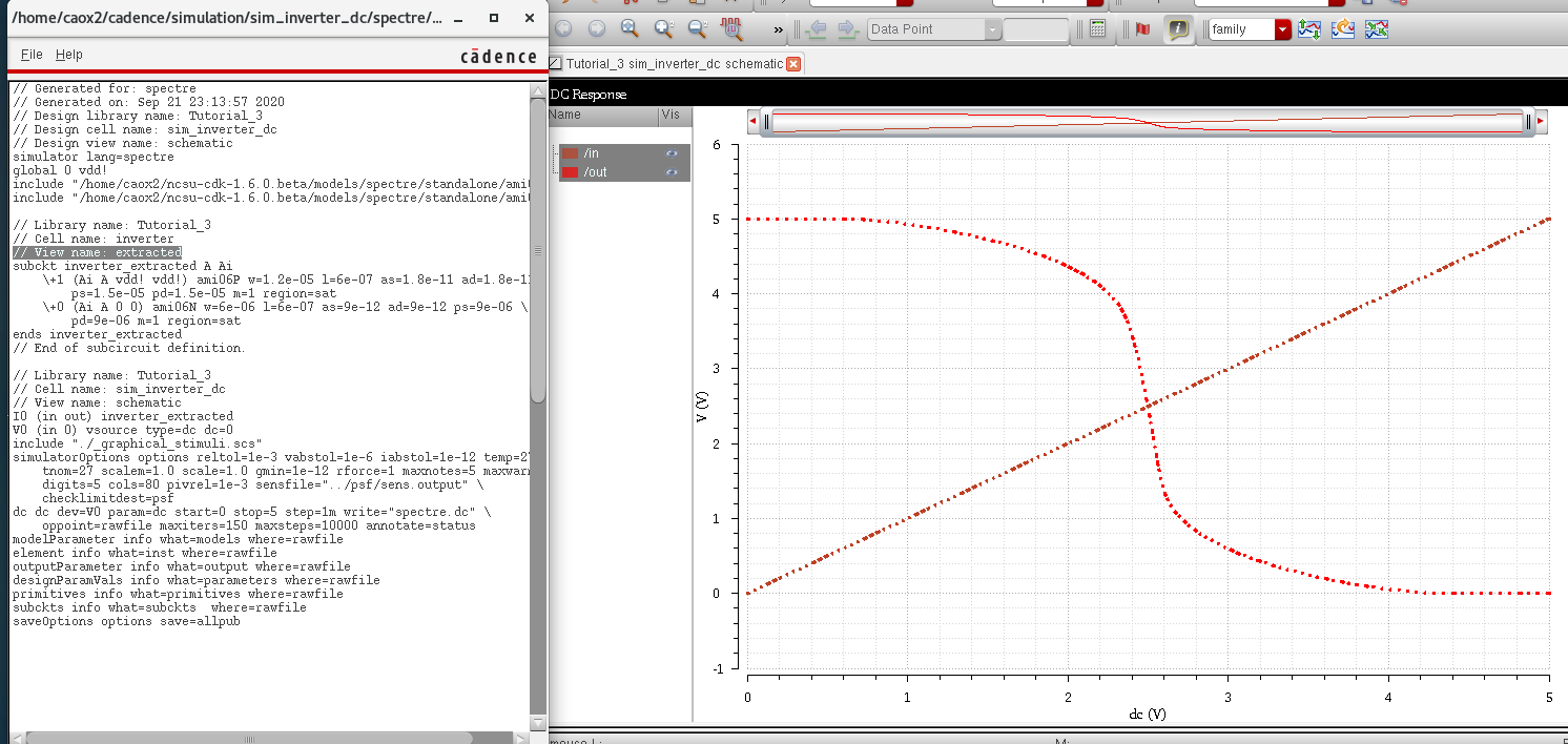
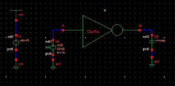
We will then start simulating the inverter, Here is the schematic of the circuit. Make sure we include vdd, but do not connect vdd to the input voltage source.
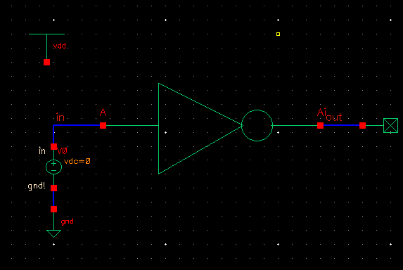
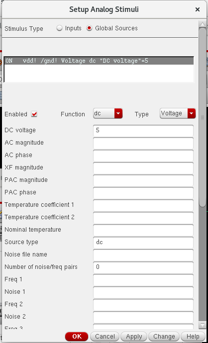
Also, remember to enable the Global Sources in the ADE, select Setup -> Stimuli.
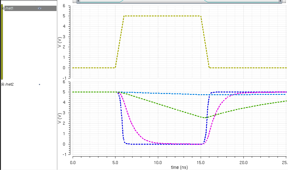
The output is as following:
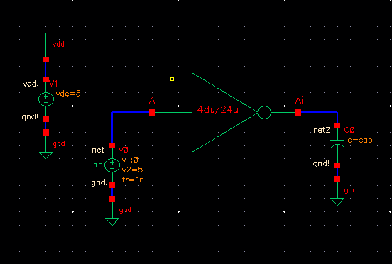
6) Simulations (100fF to 100pF capacitive load) with 48u/24u inverter.
Schematic:
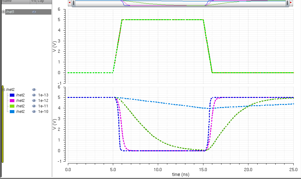
Spectre Simulation:
UltraSim:
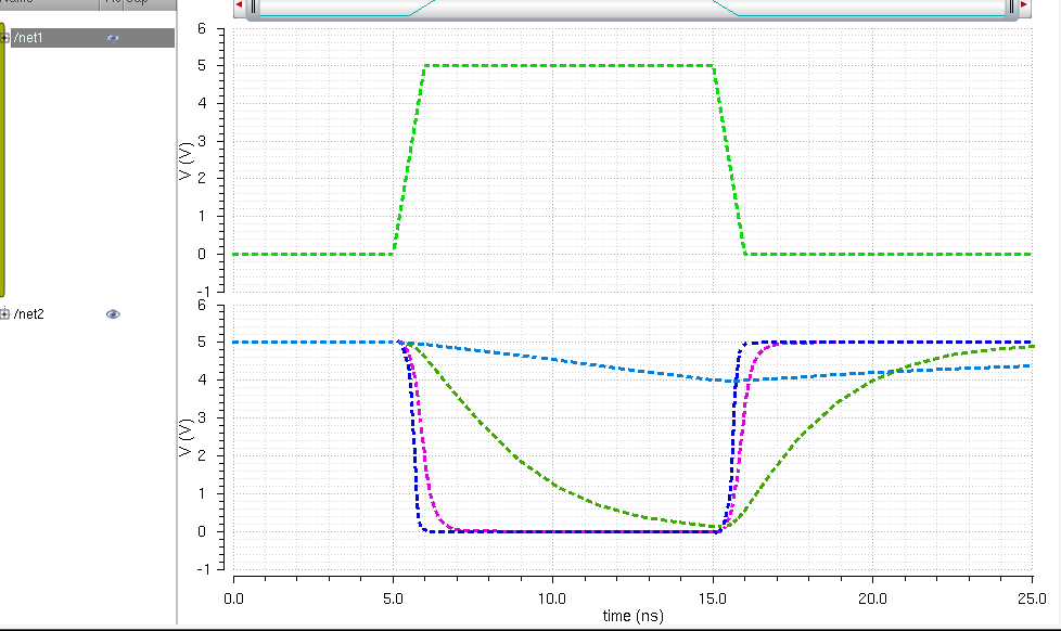
From our simulations, we can see that the four finger inverter has better output, because it has more MOSFET that allow the capacitor to charge and discharge efficiently.
For back-ups:
zipped
the library folder and the folder that has all the collected images to
the desktop, then upload them into my personal github repository for
backups.