Lab 5 - ECE 421L
Email Address: cortej2@unlv.nevada.edu
Lab Date: Sep 25, 2019-Oct 2,2019
-------------------------------------------------------------------------------------------------------------------------------------
Prelab:
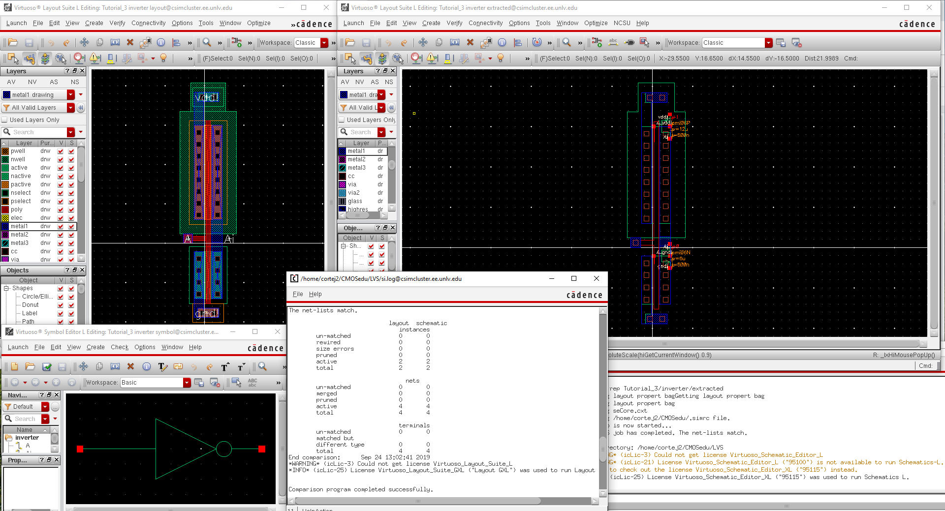
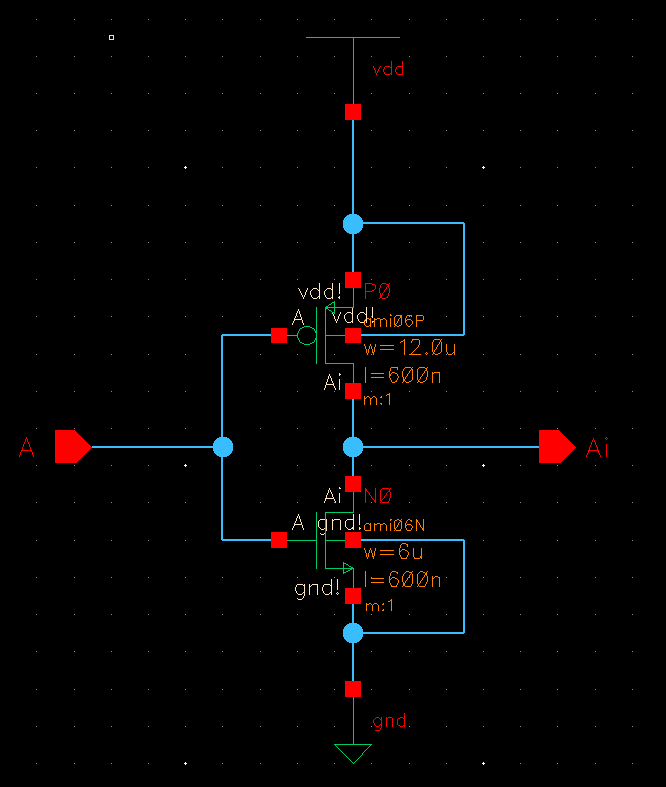
I was able to create the schematic, symbol, and layout of the CMOS inverter using a PMOS and NMOS. After which I LVS to make sure the netlist
between the schematic and extracted matched.
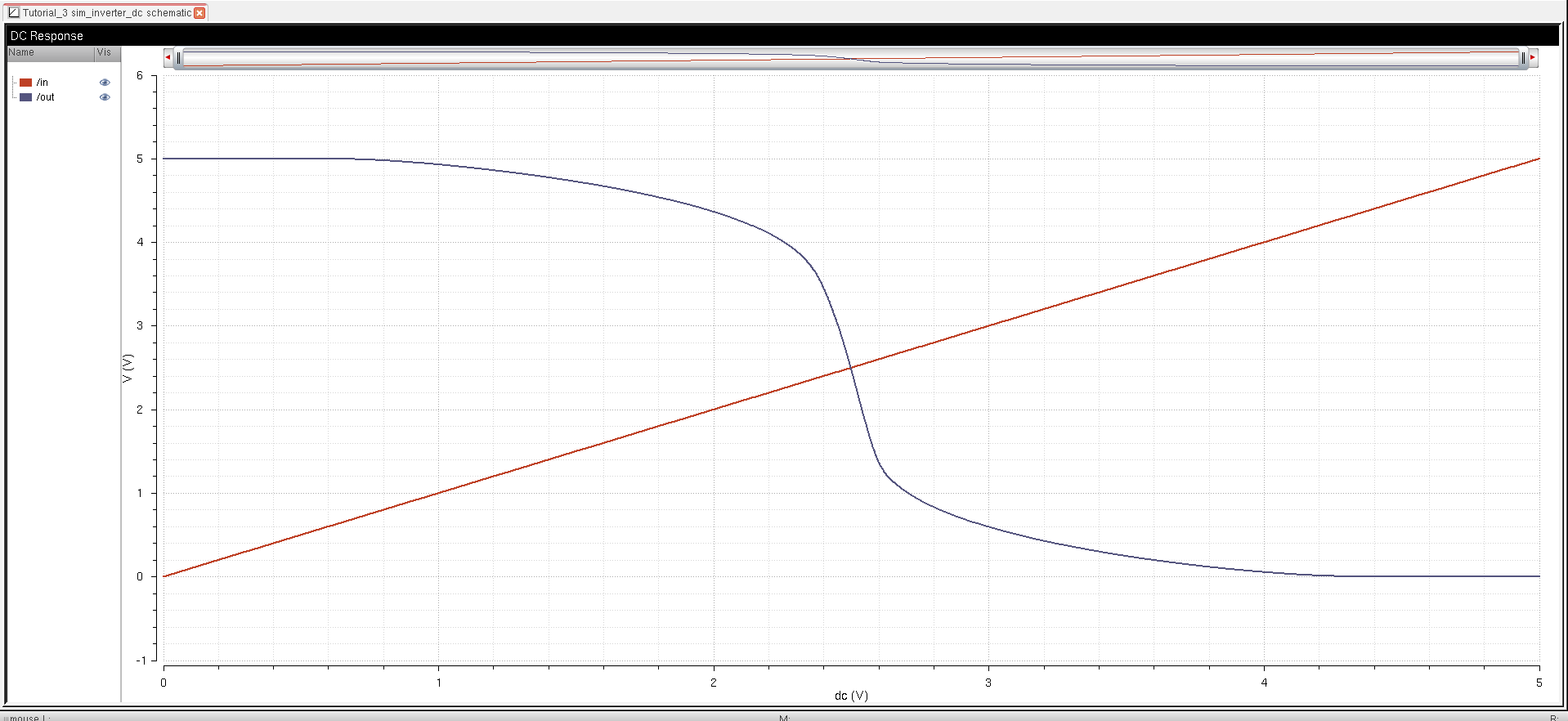
I then simulated the voltage transfer curves from the schematic seen below.
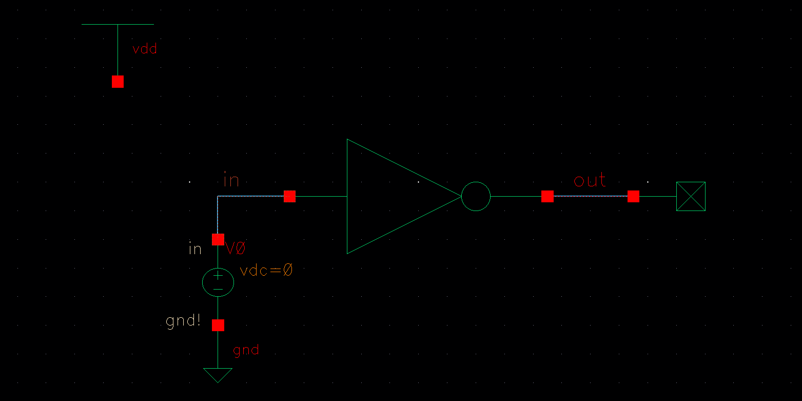
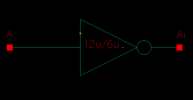
I then created a symbol for that schematic.
-------------------------------------------------------------------------------------------------------------------------------------
Lab:
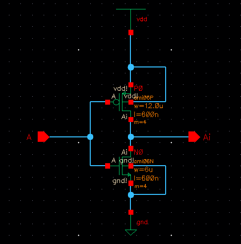
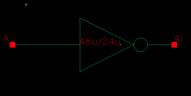
Draft schematics, layouts, and symbols for two inverters having sizes of: 12u/6u (= width of the PMOS / width of the NMOS with both devices having minimum lengths of 0.6u) 48u/24u where the devices use a multiplier, M = 4
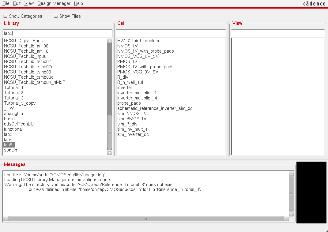
I began by creating a new folder (copied from the prelab tutorial 3) titled lab5 and opened a schematic cellview.
I then created a symbol for that schematic.
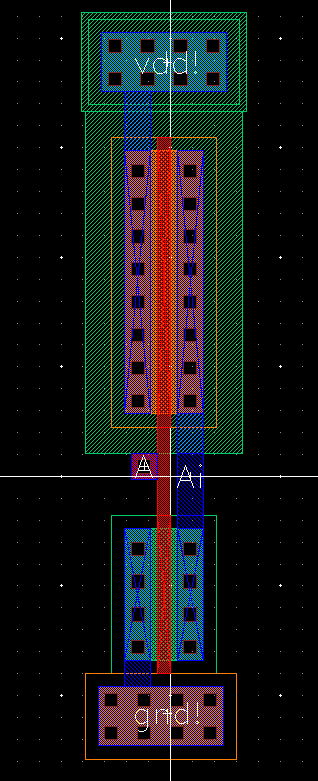
The layout for the inverter with multiplier 1 was created and is shown below.
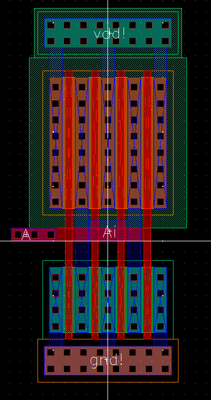
The layout for the inverter with multiplier 4 was created and is shown below.
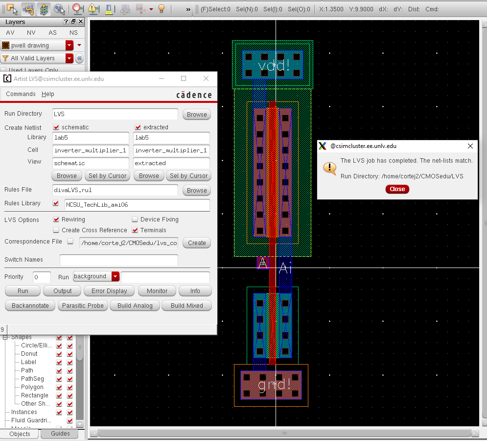
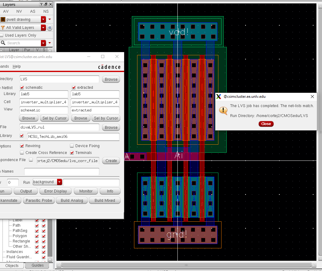
The successful LVS results for both inverters can be seen below.
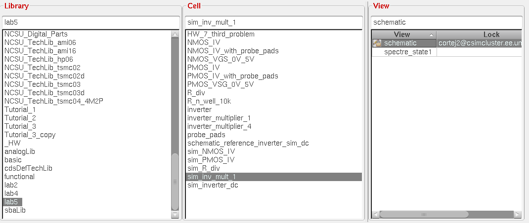
In order to simulate the newly created inverters, I created a new cell library titled sim_inv_mult_1 for the first inverter results.
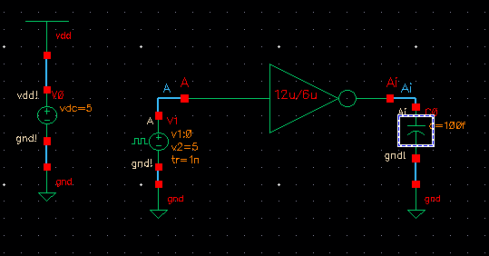
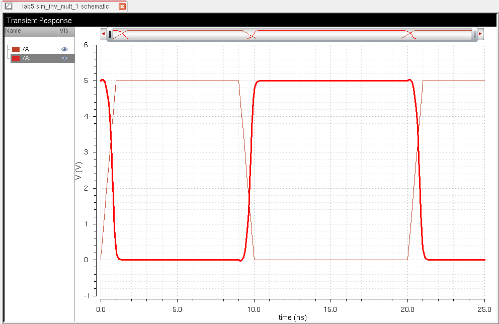
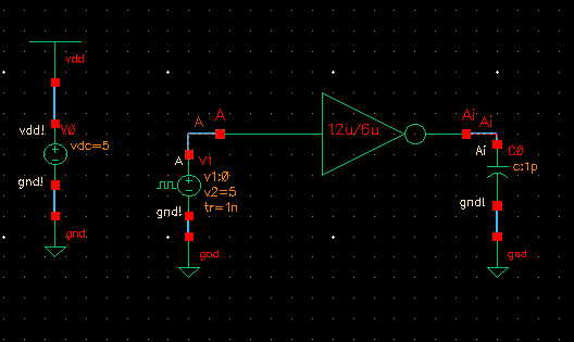
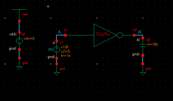
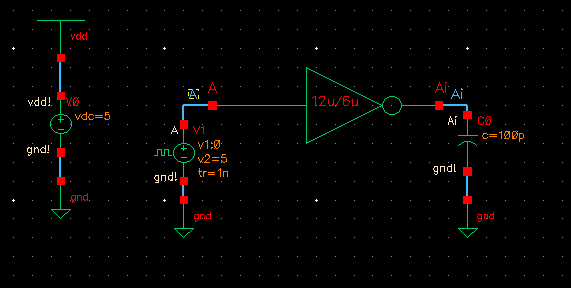
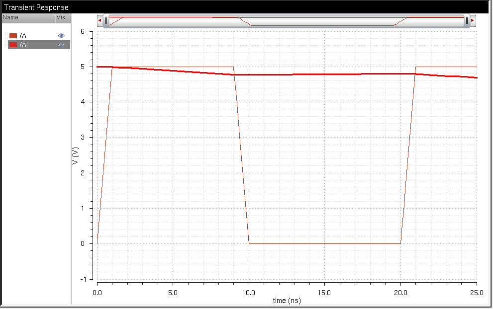
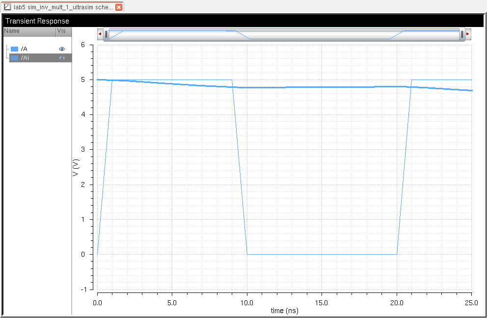
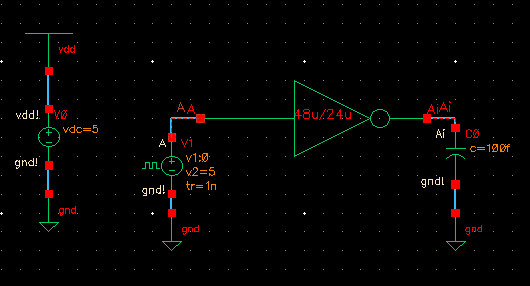
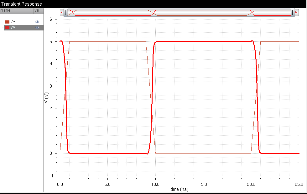
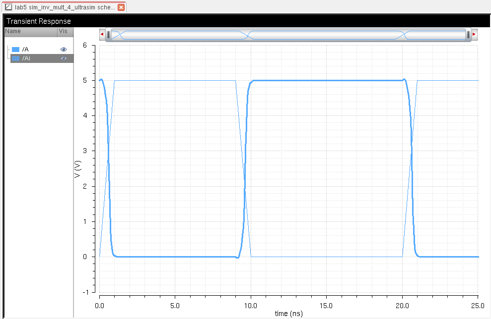
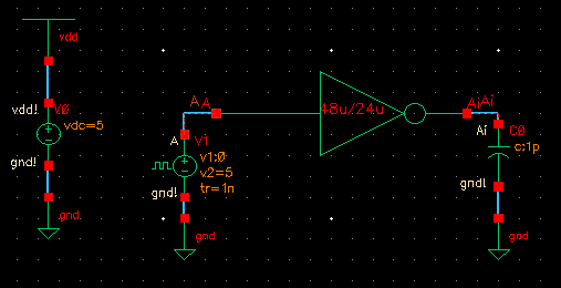
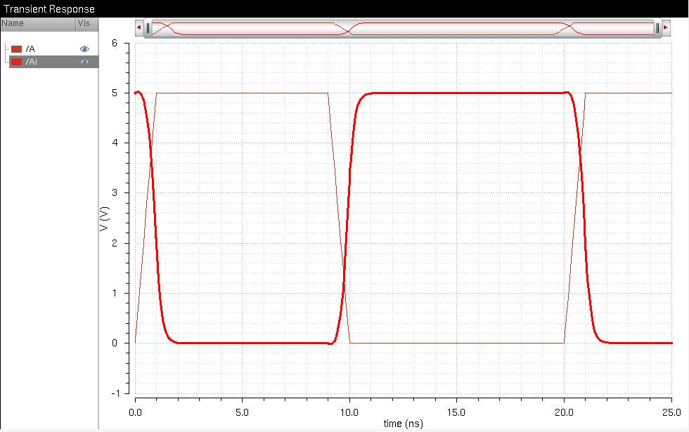
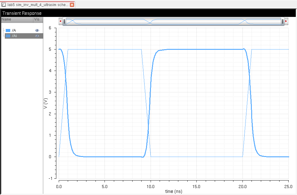
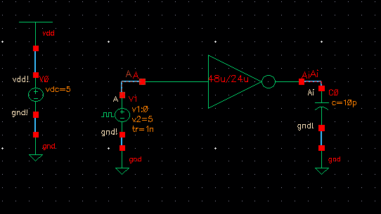
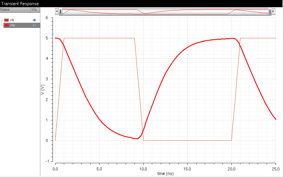
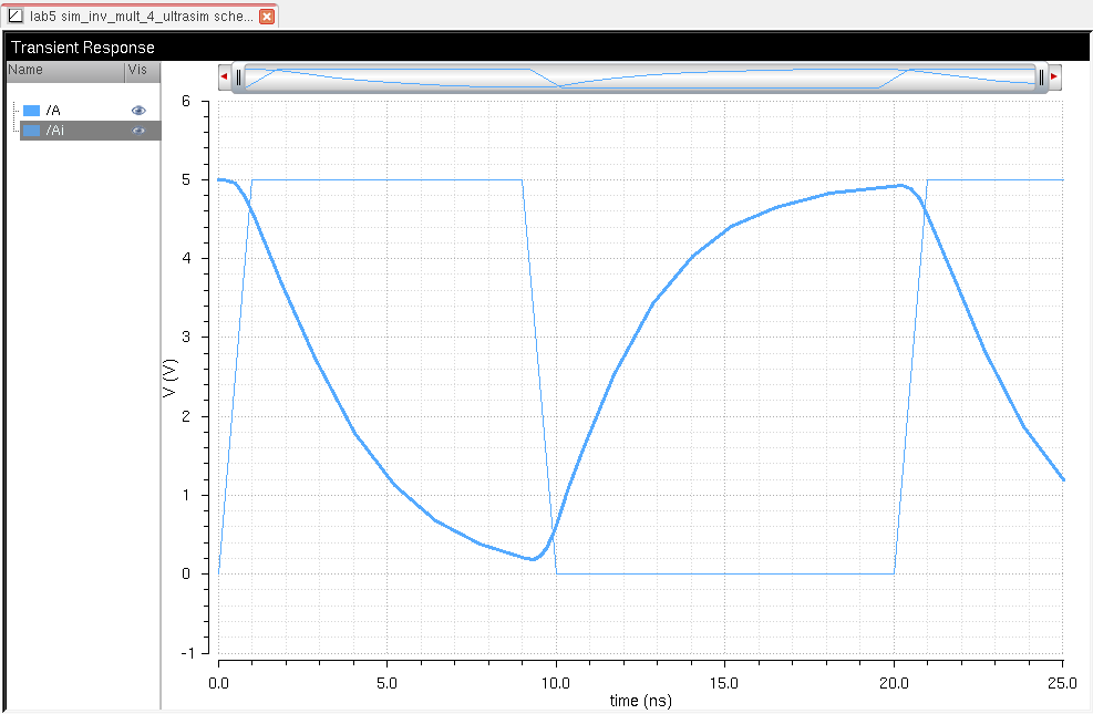
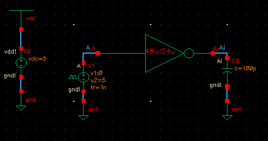
Below are the schematics and simulation results for the inverter with multiplier 1 using both spectre and Ultrasim
(spectre uses red graphs and Ultrasim uses blue graphs)
capacitor value: 100f F

capacitor value: 1p F
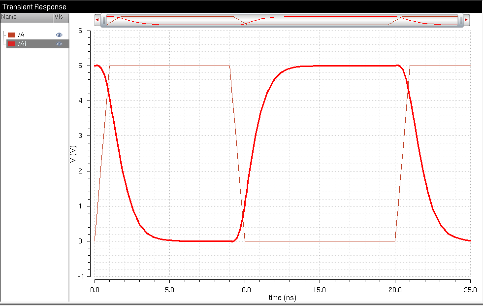
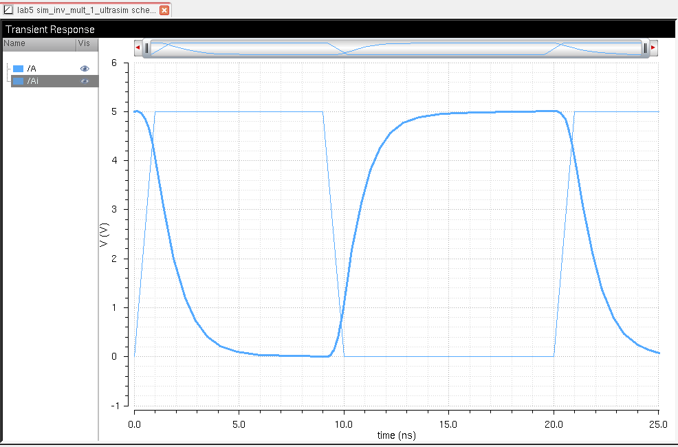
capacitor value: 10p F
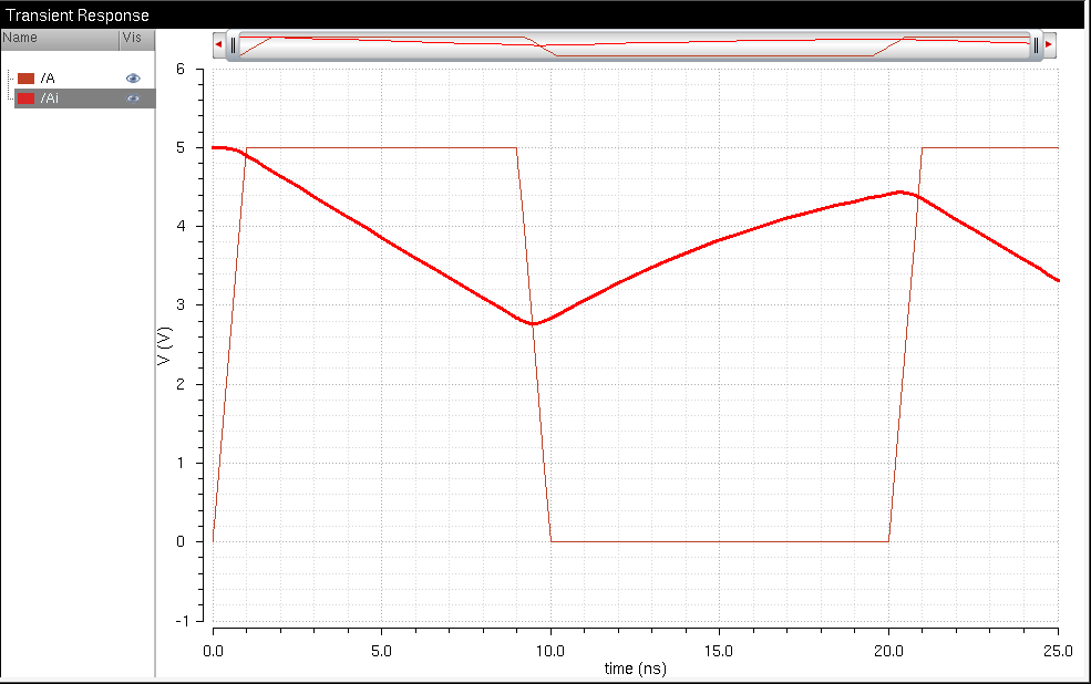
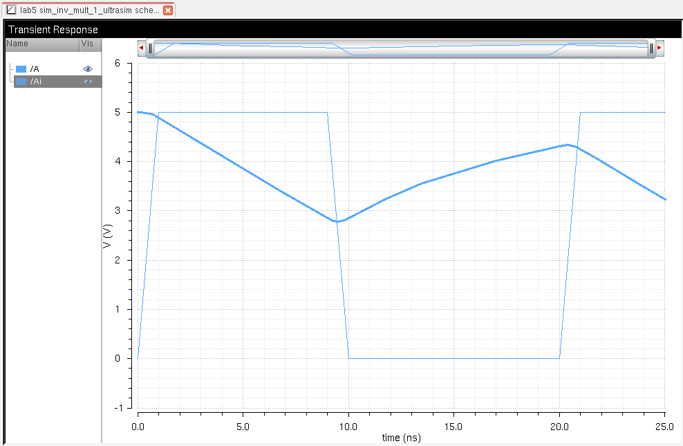
capacitor value: 100p F
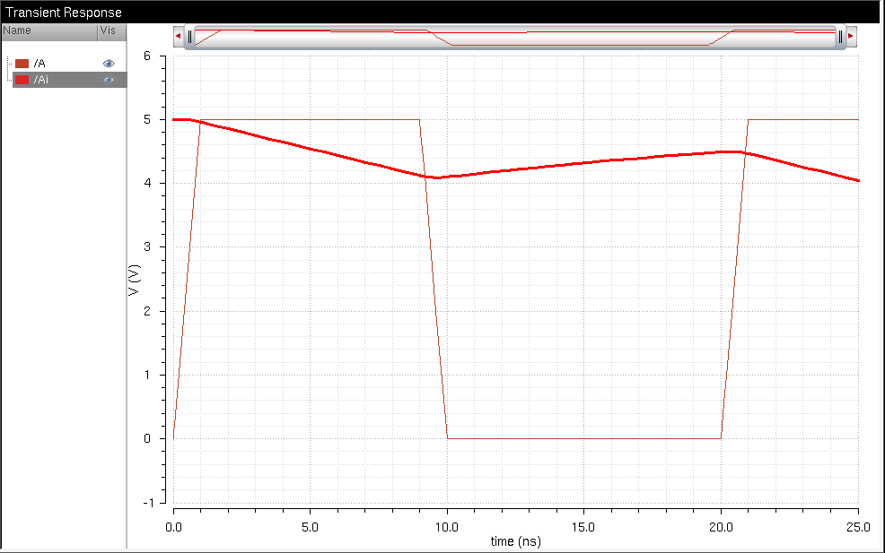
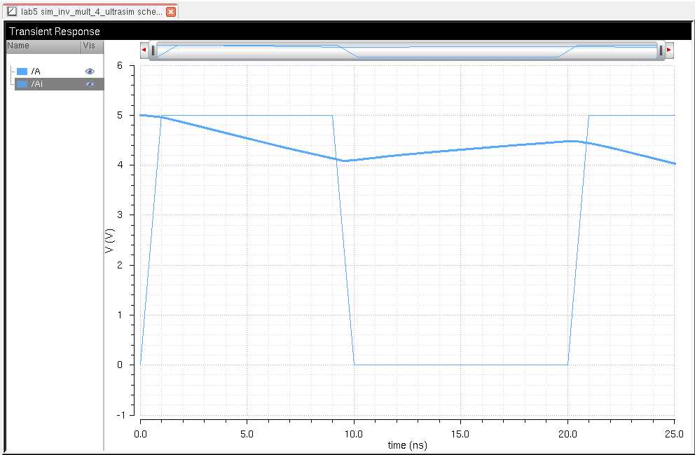
(spectre uses red graphs and Ultrasim uses blue graphs)
capacitor value: 100f F
capacitor value: 1p F
capacitor value: 10p F
capacitor value: 100p F
The Inverters used can be found through this link