Lab 1 - ECE 421L
Authored
by Yared Abraha,
abrahy2@unlv.nevada.edu
9/4/19
Lab
description
Simulating and designing a resistive voltage divider in cadence
pre lab
Requested CMOSedu acount and editing my webpage
Lab procedures:
Step 1
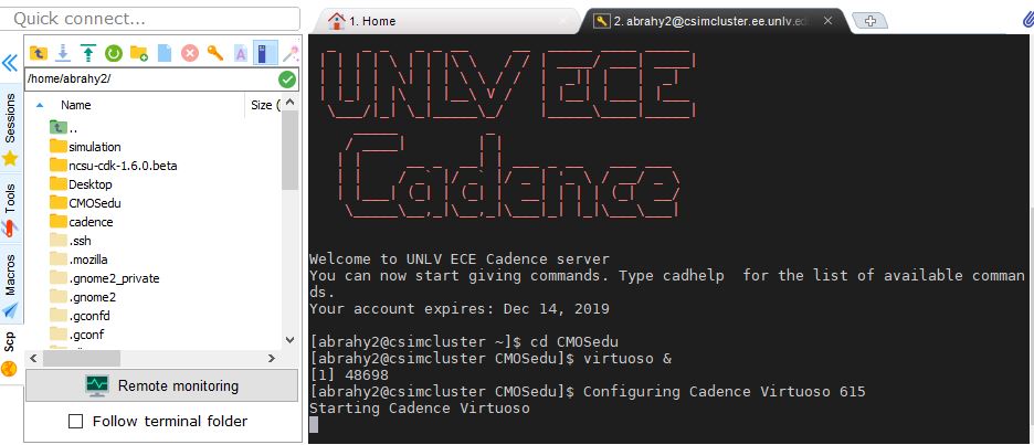
I opened
up a cadence simulation softeware for simulating my voltage divider. I
had already instaled cadence for the lecture class adn used it for the
lab.
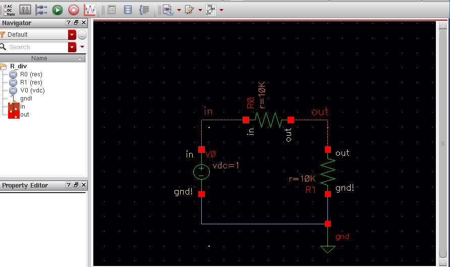
Step 2
I designed the schematics of the resistive voltage divider.
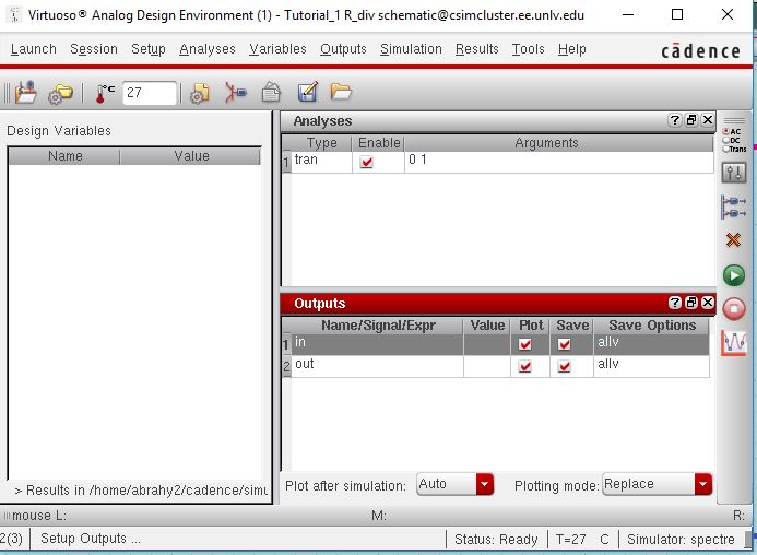
Step 3
I simulated the voltage divider cercuit.
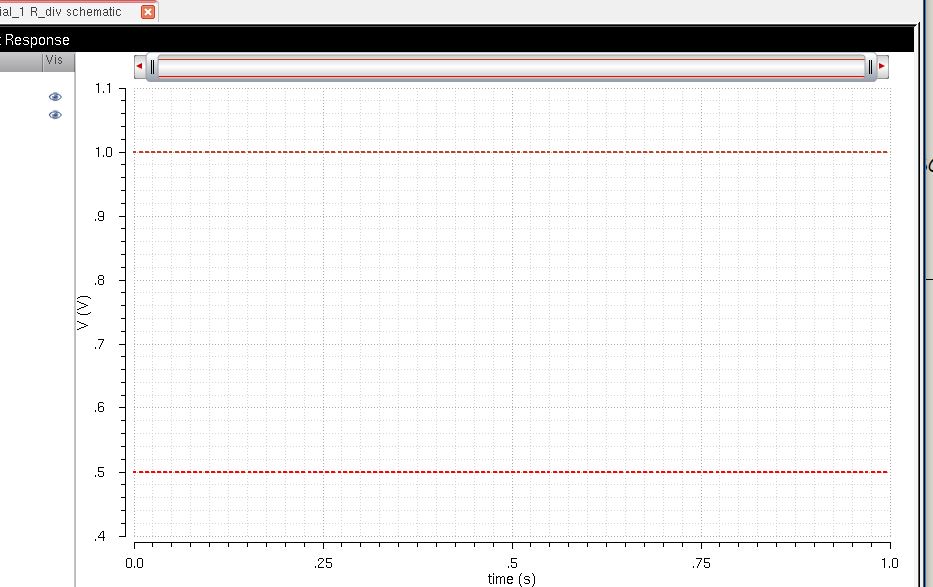
Step 4
I took the screenshot of the simulation result.
At the end i created a zipped file for back up.
Return to EE 421L Labs