Lab 7 - ECE 421L
Authored by Brett Smith (smithb25@unlv.nevada.edu)
Tuesday, November 7th, 2017
In this lab we're bussing around like a group of international tourists. The first device I made was a 4 bit inverter.
 4-bit inverter schematic |
 4-bit inverter symbol |
 4-bit inverter simulation schematic |
 4-bit inverter simulation results |
From the simulation results you can see that the increased capacitance on the output increases the delay of the circuit as would be expected becuase of the larger RC time constant.
I then built a NAND, NOR, AND, and OR gates as well as a 2-to-1 demux and made them into an 8-bit devices. NOTE: the rest of my simulations were done using Stimuli instead of a specific simulation schematic.
 NAND symbol |
 NAND symbol |
 8-bit NAND schematic |
 8-bit NAND symbol |
 8-bit NAND simulation results |
|
 NOR symbol |
 NOR symbol |
 8-bit NOR schematic |
 8-bit NOR symbol |
 8-bit NOR simulation results |
|
 AND symbol |
 AND symbol |
 8-bit AND schematic |
 8-bit AND symbol |
 8-bit AND simulation results |
|
 OR symbol |
 OR symbol |
 8-bit OR schematic |
 8-bit OR symbol |
 8-bit OR simulation results |
|
 8-bit inverter schematic |
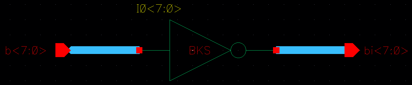
 8-bit inverter symbol |
 8-bit inverter simulation results |
|
 2-to-1 demux symbol |
 2-to-1 demux symbol |
 8-bit 2-to-1 demux schematic |
 8-bit 2-to-1 demux symbol |
8-bit 2-to-1 demux simulation results |
|
The last step of the lab was to do the same thing with a full adder and then do the layout for that full adder.


Wow that was a lot! The library for my design can be downloaded here. Both my lab and this website have been backed up.