Lab 2 - ECE 421L
patelp3@unlv.nevada.edu
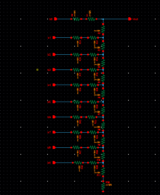
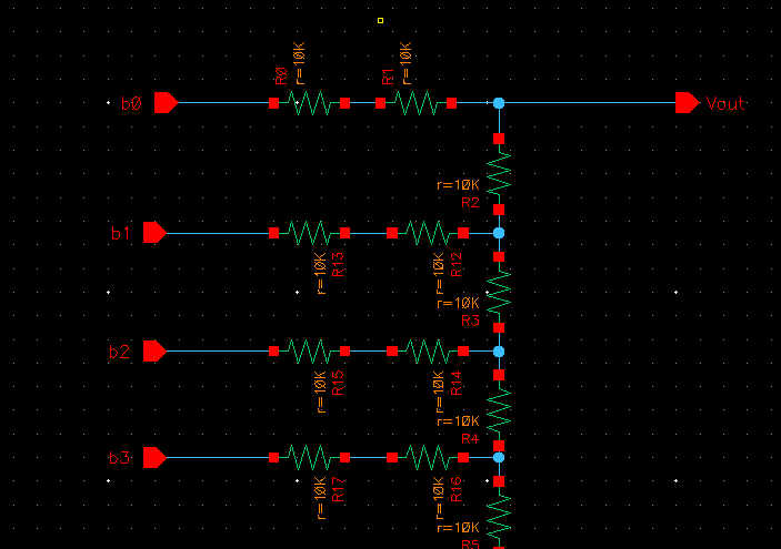
As
the lab instructed, I used two 10K Ohms resistors in series for the 2R.
The total resistance of this circuit should equal to 10K Ohms as
calculated.
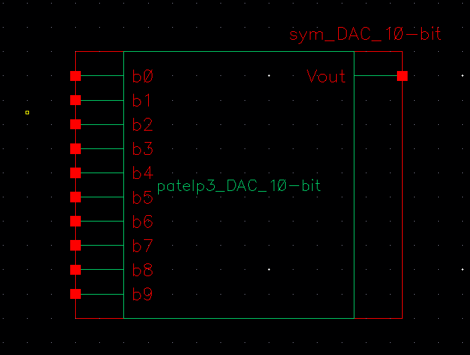
Next,
I created a symbol out of the above circuit. Using this symbol, I can
see the input pins b[0:9] and output pin Vout clearly and it that will
make it easier for me to connect it in a more complex circuit. Overall,
a symbol is used to simplify the ciruit.
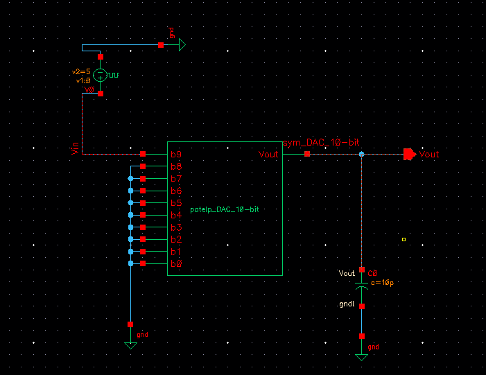
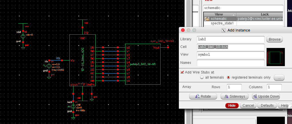
Then
I replaced the old DAC symbol with my new one in the schematic that was
given to us. I originally messed up with the input pin numbering and
named them b[9:0] instead of b[0:9]. Though the connection doesn't make
a difference for this project, it can create a mess if you connect the
wrong pins so I changed it later into the lab.
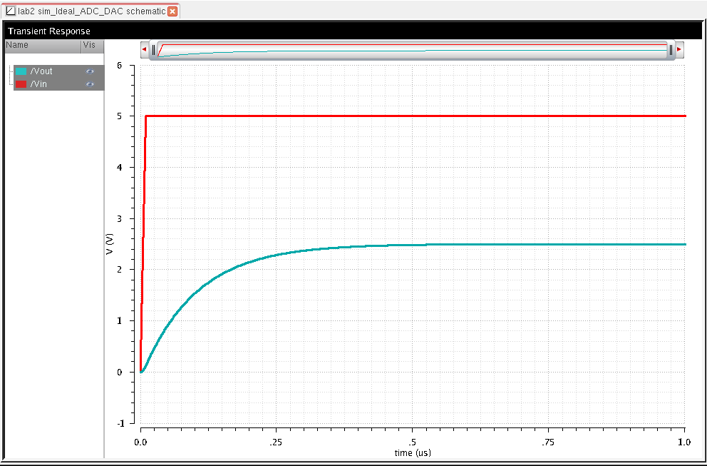
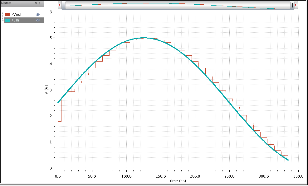
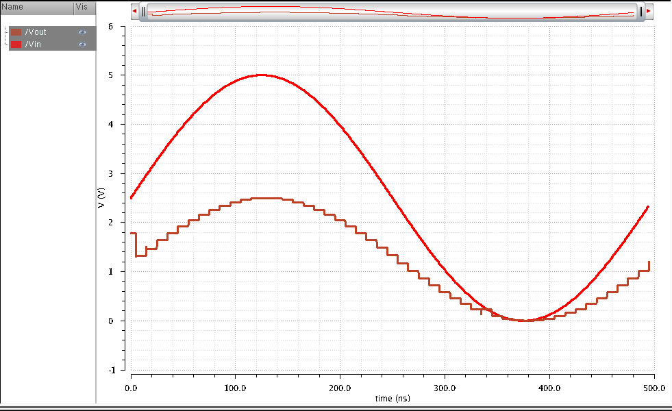
Below is the simulation of the circuit above. As we learned in the prelab, the two plots show a conversion in increments.
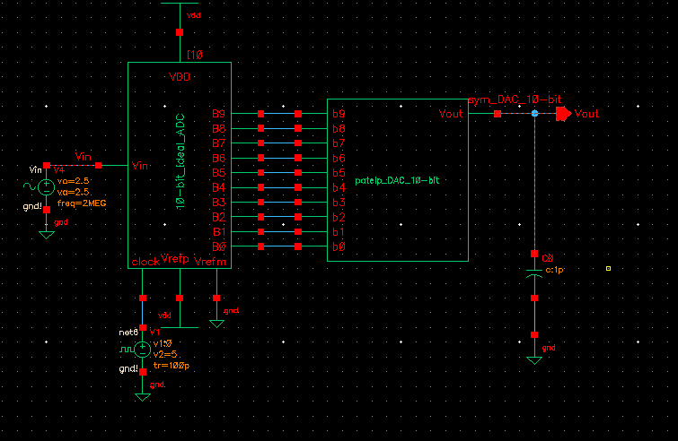
Here, we add a load of R=10K Ohms to our DAC.
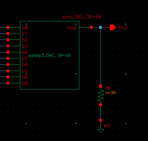
As
seen below, the resistive load changes the amplitude of the output. As
the resistance increases, the output decreases. Here, I used 10K load.
The output is approximately 50%.
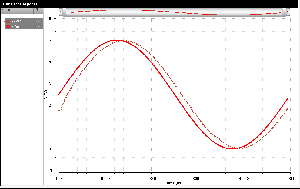
Next
I removed the 10K load and added a capacitor of 1pF instead. The
capacitor gives a smooth, slightly delayed output and the zigzag
increments are gone.
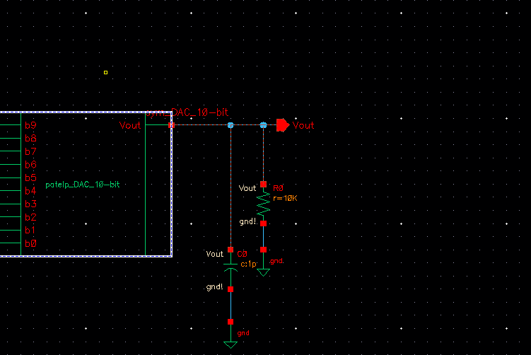
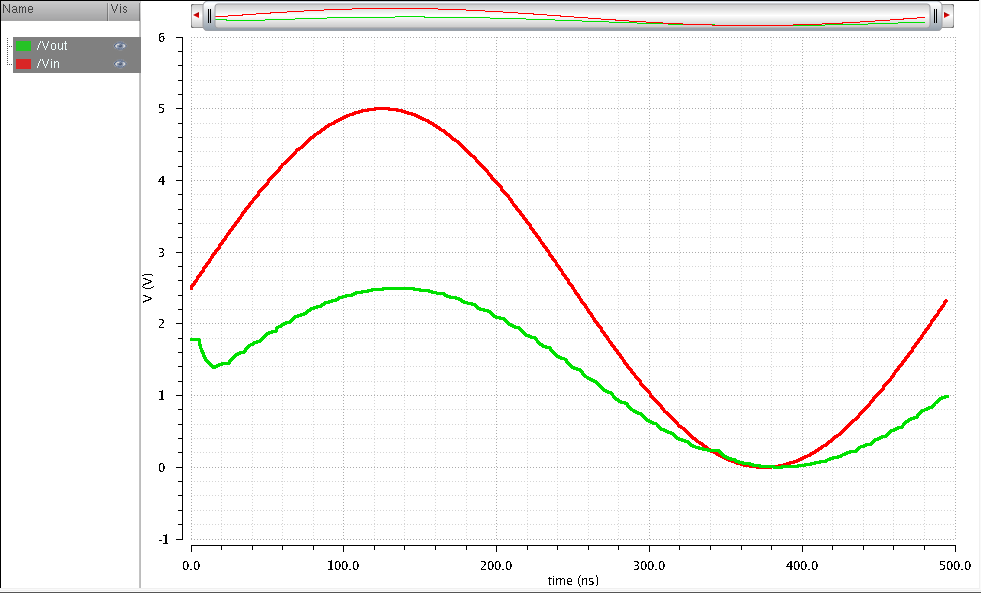
For
the next experiment, I added a 10K load in parallel with the 1pF
capacitor. As I hypothesized, the output was a smooth, delayed curve
due to the capacitor and had about 50% output due to the resistor.
In
the next experiment, I removed the load of 10K Ohms and left only the
1pF capacitor at the output wire. For the input, I grounded b[0:8] and
added a VPulse from 1 to 5 at b9. This way, we can simulate a delay. We
know the resistance total is R=10K and the capacitance is 1pF. Using
this information, we can assume the delay will be about t =
0.7(10K)(1p) = 7ns.