EE 421L
Project
Authored
by Jeremy Morgan
Email: morgaj7@unlv.nevada.edu
Due: 11/15/2017
Lab Description:
Design of an EVEN parity checking circuit having a 9-bit input word.
The parity checker will Output a [1] when the EVEN check is valid and a [0] when the EVEN check is [invalid]
Inputs:
8 bits of Data
1 Parity bit
Outputs:
[1] if valid
[0] if invalid
Lab:
Part 1: Components of Parity Checker)
Inverter:
Schematic
Symbol


Layout
Extracted


DRC

LVS

Simulation + Results

XOR:
Schematic
Symbol


Layout
Extracted


DRC

LVS

Simulation + Results


Part 2: Parity Checker)
How it works:
Inputs:
8 bits of Input: D[0 - 7]
1 Parity Bit: [P]
Outputs:
CHECK
Process:
Using XOR gates we will see if the number of set bits (bits that equal 1) are EVEN or ODD
XOR TRUTH TABLE

As the inputs are entered through the XOR gate a [0] is the OUTPUT if the number of [1]'s of the INPUT are EVEN.
Going
through multiple XOR gates we will reduce the inputs to a single value
(1 or 0) depending on if the number of set bits of the input are odd or
even
We will then XOR that value (0 if even and 1 if odd) with our PARITY BIT (0 or 1)
If the Parity bit is set to [0] and the inputs are [EVEN] then we will output a [0]
We will then invert this value to produce a OUPUT of [1] if the inputs are EVEN and the parity check is set [0]
If our inputs are ODD and the parity check is [1] then we will output a 1
All else will output a [0]
Parity Checker:
Schematic
Symbol


Layout
Extracted


DRC

LVS

Simulation
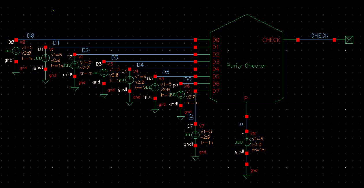
Simulation Outputs:

Outputs results:
Inputs[D0-D7]: 00111110
Parity[P]: 1
Ouput[CHECK]: 1
Inputs[D0-D7]: 11111111
Parity[P]: 0
Ouput[CHECK]: 1
As you can see when the INPUTS are EVEN and the PARITY BIT is [0] the OUTPUT is [1]
The Parity Checker works as intended, outputting a [1] for a Valid EVEN check and a [0] for everything else!
PROJECT DIRECTORY (zip file): HERE
Return to EE 421L Labs