Lab 3 - ECE 421L
Authored
by Dominic Hryciuk,
email: hryciuk@unlv.nevada.edu
Last edited on 19 September 2017
The focus of this lab is the layout of the DAC that was designed and simulated in Lab 2.
The first step is to create a 10k resistor using an n-well and two n-taps. Using the provided equation for resistance, the desired length of a resistor layout can be determined.

The R-square value is given by the C5N process
characteristics, which is 855 ohm/square for n-wellls. For a selected
width of 3.6um, the length for a 10k resistor is about 42.3um.

However,
Virtuoso uses slightly lower sheet resistance values, approximately 800
ohm/square. The above length will create a resistor lower than what is
expected.

With
the lower Rsquare value, the length of the resistor is recalculated and
laid out. Using 3.6um width, the length is calculated to be 45um. The
resistance this time is little higher but is closer to 10k.

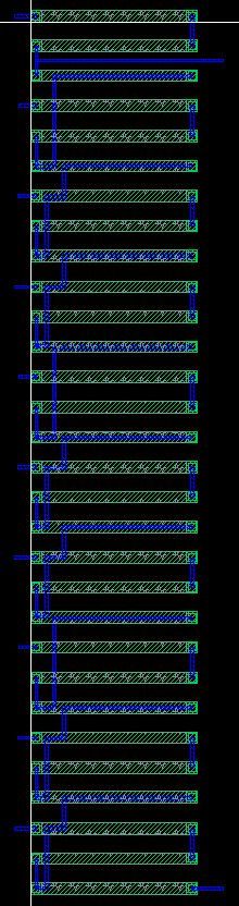
The
layout of the R-2R DAC is simple and repeating. The resistors are
placed on the same x-position but different y-positions. The input pins
for 10 bits is on the left, and the Vd and ground pins are on the right.
This results in a compact design where all the n-wells are near each other.


Click for a larger image
The layout passes DRC properly, but LVS has one bad connection between resistors. Otherwise, the netlists are the same.


The layout and schematic can be analyzed by downloading the zip file here.
Return to EE 421L Labs
Return to Student Directory