Lab 05 - ECE 421L
Authored
by Aaron Escobedo
escoba3@unlv.nevada.edu
10/2/17
PreLab - Complete Tutorial 3
Here is some of my data from completing the Tutorial 3
By using the copy and paste method described in the lab, I was able to create a new schematic and assocaited symbol
Following that, I create the associated Layout designs, again following the examples given in Tutorial 3
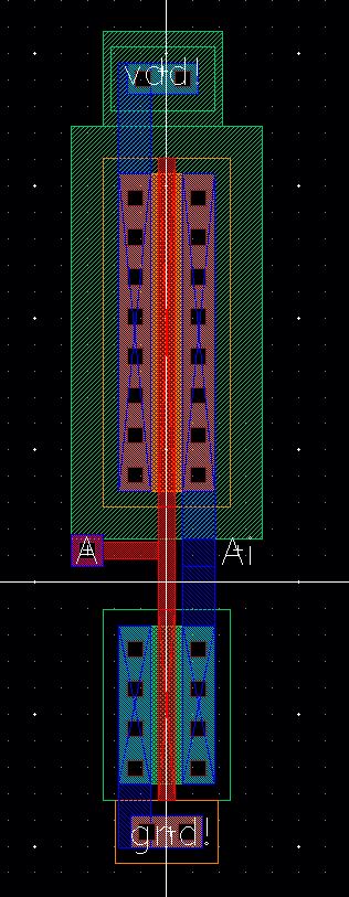
Layout View | 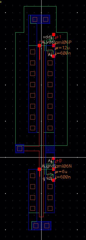
Extracted View |
Next, we need to simulate this inverter, I set up the following schematic
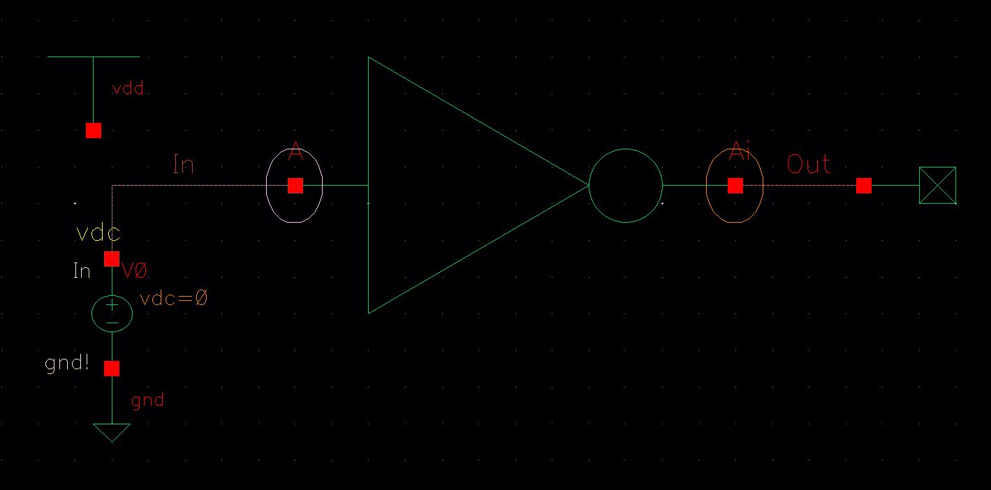
This produced the following results
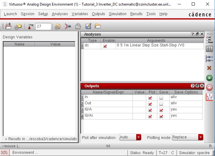
ADE Parameters | 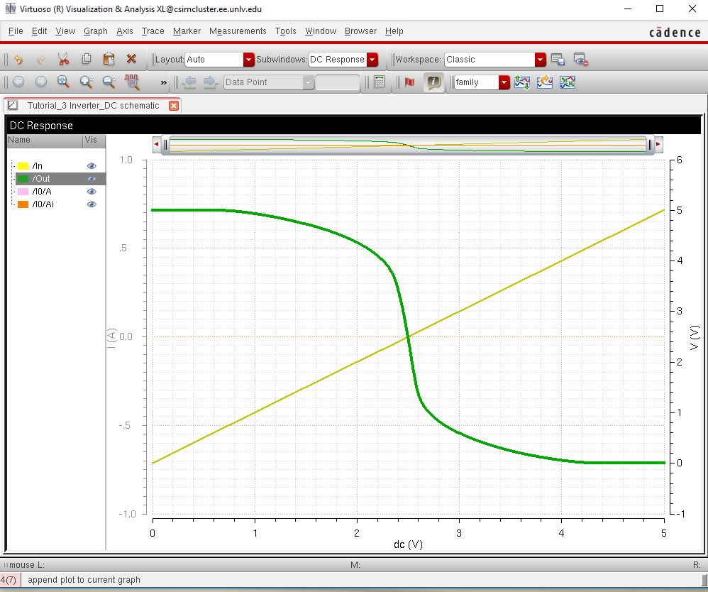
Resulting graph from schematic |
This completed Tutorial 3 and the prelab
Lab Work
- Draft schematics, layouts, and symbols for two inverters having sizes of:
- 12u/6u (= width of the PMOS / width of the NMOS with both devices having minimum lengths of 0.6u)
- 48u/24u where the devices use a multiplier, M = 4
Since
the prelab helped us complete the 1st design (12u/6u Inverter) I used
that design for the first part and created a new one with a multiplier
of 4

Initial Schematic (m=1) | 
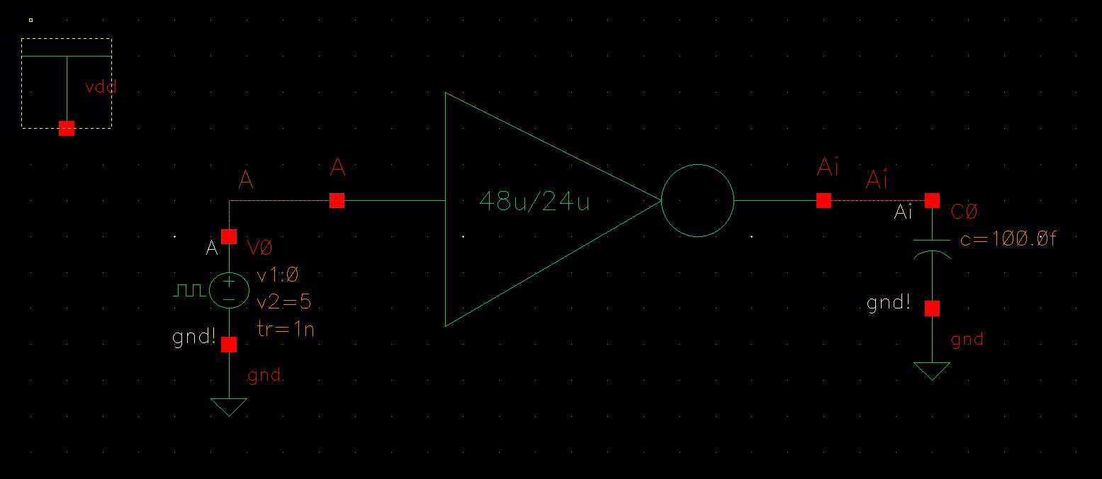
Secondary Schematic (m=4) |
Layout view of the Schematic for 12u/6u | 
Layout view of the Schematic for 48u/24u |
Extracted View of Layout for 12u/6u | 
Extracted View of Layout fort 48u/24u |
Click on image to enlarge

Passed LVS for 12u/6u Inverter | 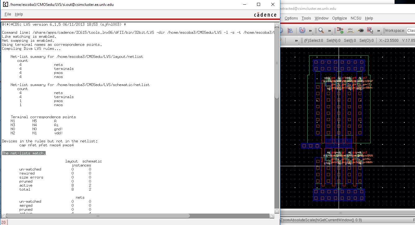
Passed LVS For 48u/24u Inverter |
- Using SPICE simulate the operation of both of your inverters showing each driving a 100 fF, 1 pF, 10 pF, and 100 pF capacitive load
12u/6u Simulation
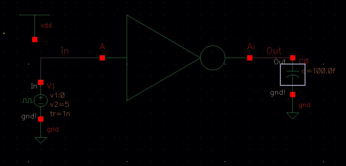
I
created the folllowing schematic to simulate the inverter with a
capacitive load of varying values; by using "q" one can quickly change
the parameters of the capacitor. Additionally, the DC source is a pulse
with a 1ns rise and fall time, and a 12ns pulse width.
here are the results from various capactive loads

100fF Load | 
1pF Load | 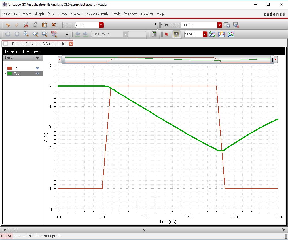
10pF Load | 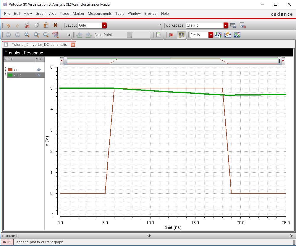
100pF Load |
Here,
we can clearly see it takes more and more time to switch from a high
state to a low state as the capacitor value increase. This makes sense
as the value of the capacitor has a large impact on time constants
within the formula;
Change in voltage = (V[final] - V[initial])(1-e^[-{t/RC}]
46u/24u Simulation
In a similar manner, I first created the following schematic;
And these are the following results from this circuit with varying capacitive loads.
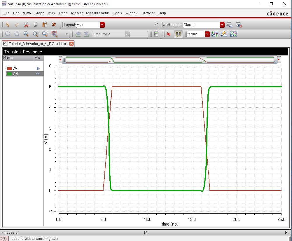
100fF Load | 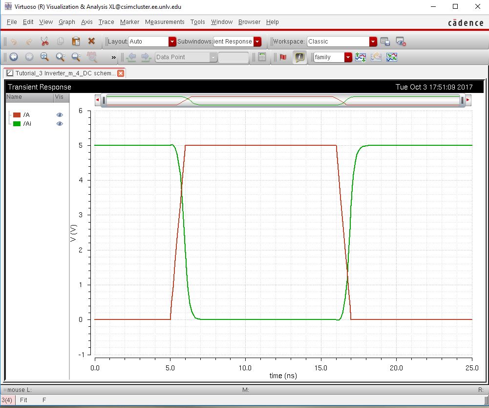
1pF Load | 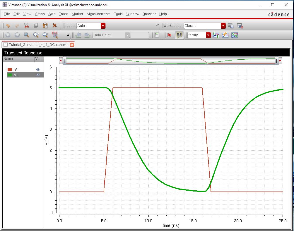
10pF Load | 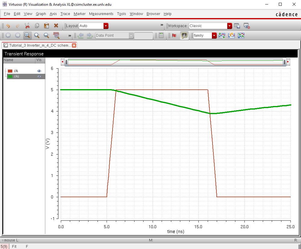
100pF Load
|
In
a simliar manner, how quickly it changes states varies depending upon
the value of the capacitor, however, this one switches faster than the
12u/6u Inverter. This too makes sense as the inverter has more surface
area associated with it and thus can allow more current to flow
through, results in a quicker state change.
- Use UltraSim (Cadence's fast SPICE simulator for larger circuits at the cost of accuracy) and repeat the above simulations
Now, we will use a different simulation parameter, Ultrasim to compare the results of our schematics
| 12u/6u Specture | 12u/6u UltraSim | 48u/24u Specture | 48u/24u UltraSim |
| 100fF Load | | 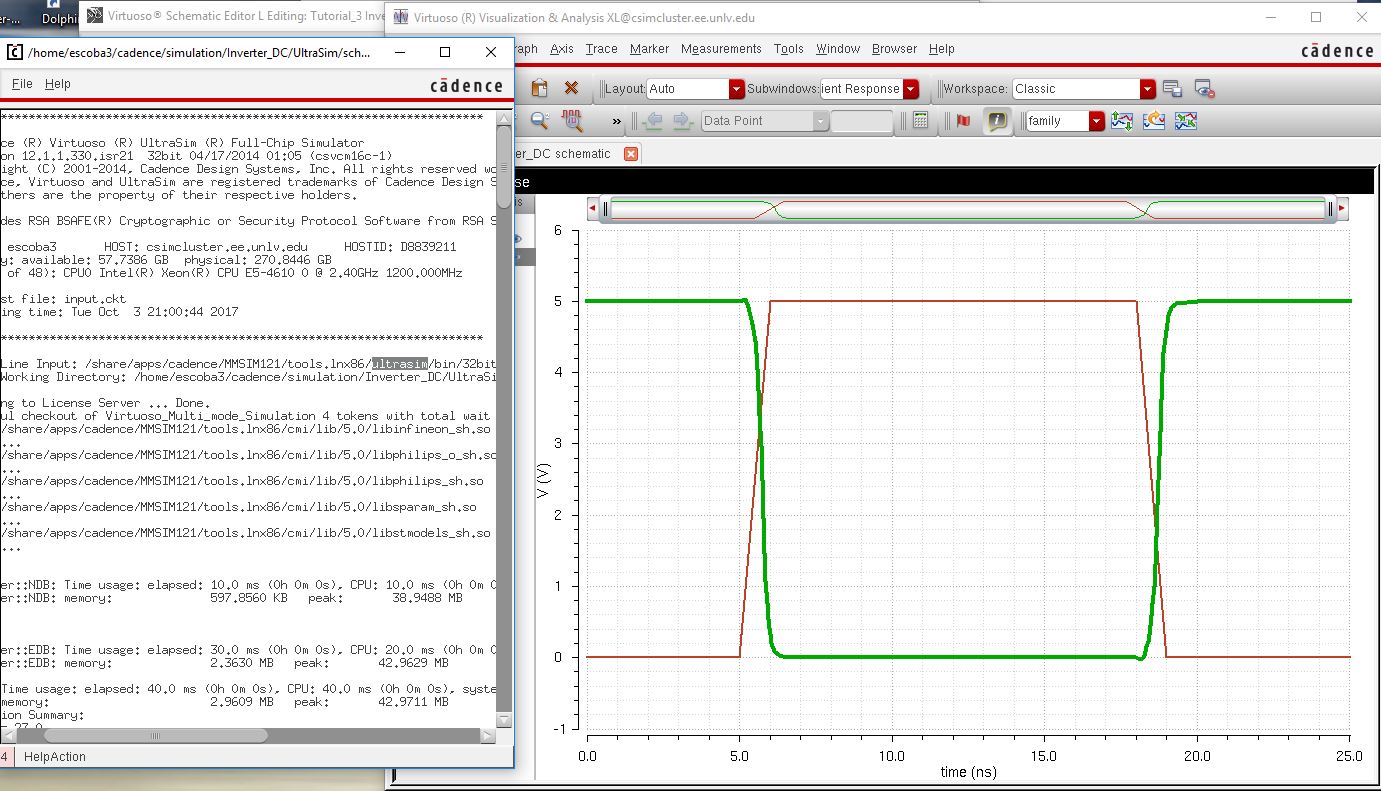 | | 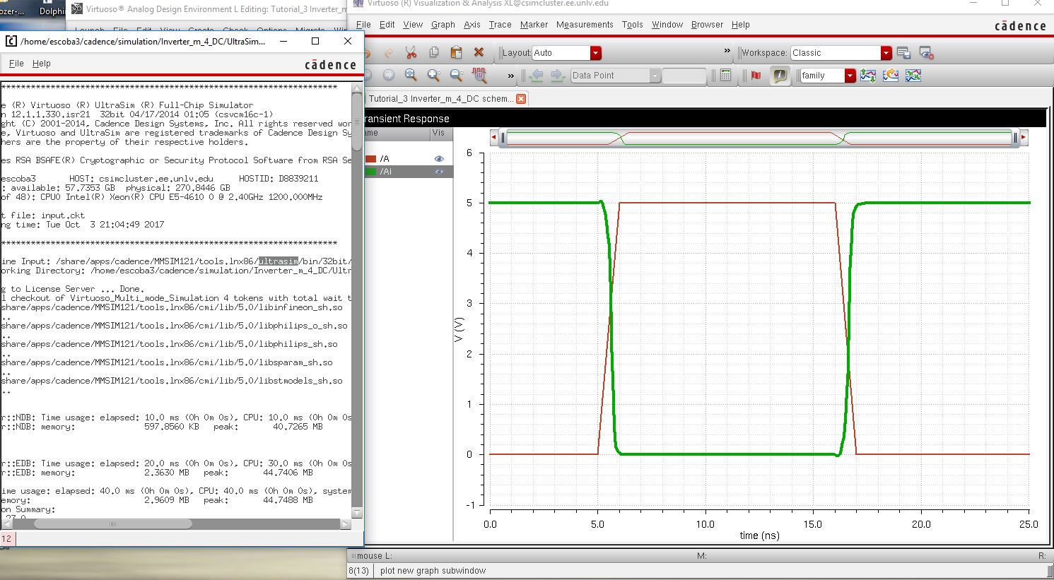
|
| 1pF Load | | 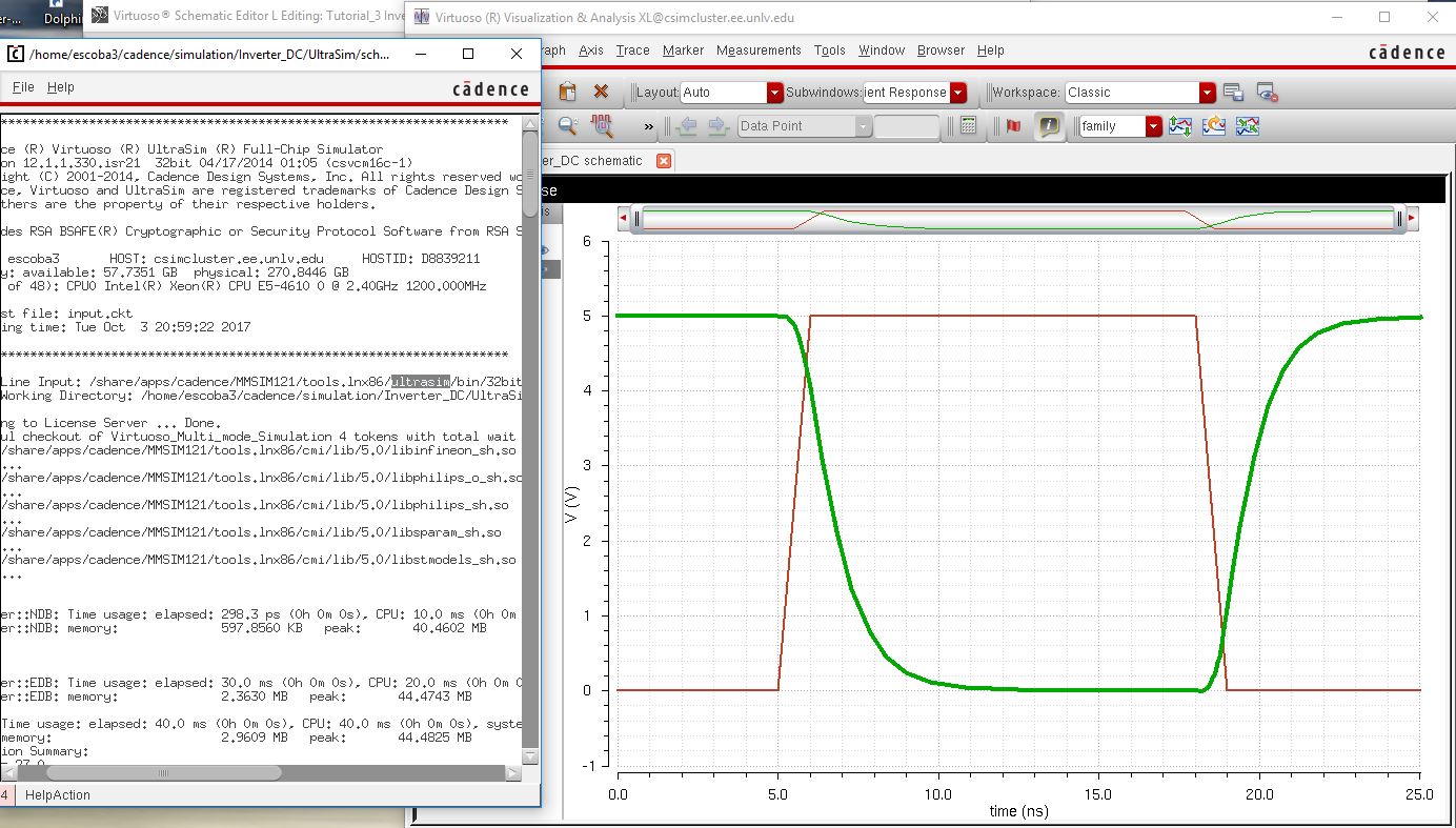 | | 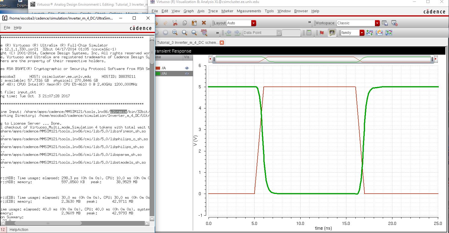 |
| 10pF Load | |  | |  |
| 100pF Load | |  | |  |
By
seeing everything next to each other, we can see that the quicker,
UltraSim simulation actually is not far off from our initial simulation
at all! It could be that this is a simple circuit design, but it works
rather well for us here.
This concludes our lab 5 experiments and procedures.
Link to Files for lab 5
Return to Students
