Lab 03 - ECE 421L 

Authored by :: Aaron Escobedo

9/20/17

Prelab

We will first finish the tutorial 1 as described in the Prelab work;

Our orginal R_div circuit is shown first

http://cmosedu.com/jbaker/courses/ee421L/f17/students/escoba3/Lab3/R%20Div%20Schematic%201.JPG

Following that, we create a symbol for it in order to gain experience in this process. 

http://cmosedu.com/jbaker/courses/ee421L/f17/students/escoba3/Lab3/R%20Div%20Symbol%201.JPG

From here, we will attempt to create a layout of this design in the layout view, this is done by selecting the following options shown below. 

http://cmosedu.com/jbaker/courses/ee421L/f17/students/escoba3/Lab3/Creating%20a%20N_well.JPG

From here, we will create our initial N_well resistor, but importantly, we must ask how we decided to choose the size of this resistor. This was done by following a few parameters. The initial resistance of this type was mentioned to be 800 Ohms per square, thus we can calculate the following if we desire a 10k resistor.

http://cmosedu.com/jbaker/courses/ee421L/f17/students/escoba3/Lab3/N_well%20resistance%20calucation.JPG

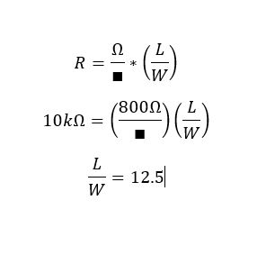
Following the tutorial, it was suggested to create a 4.5 micron length, thus create a 56.1 width. since (4.5)(12) = 56.1

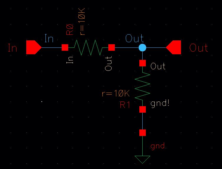
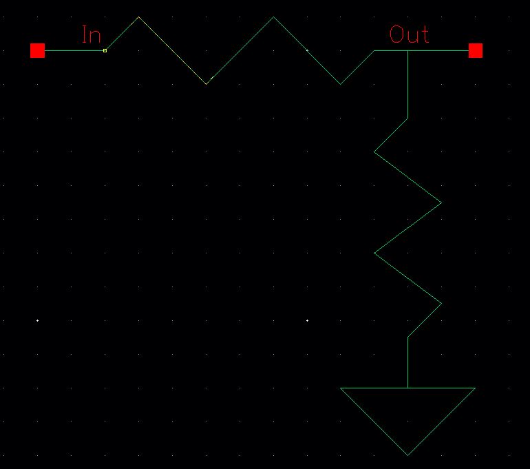
Here is our initial N_well resistor;

http://cmosedu.com/jbaker/courses/ee421L/f17/students/escoba3/Lab3/Initial%20N_well.JPG

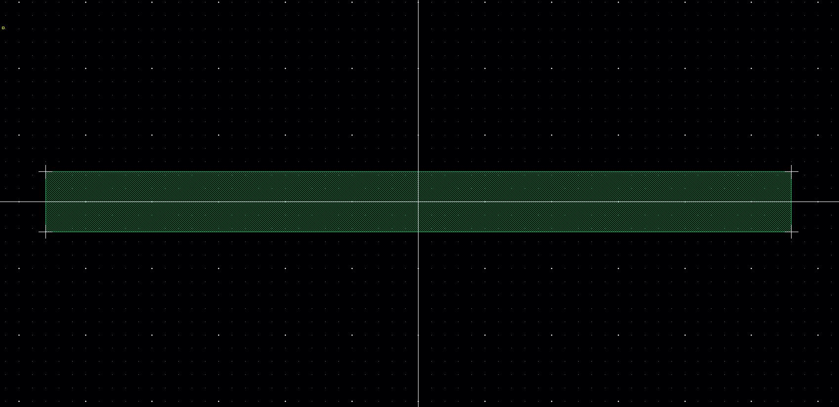
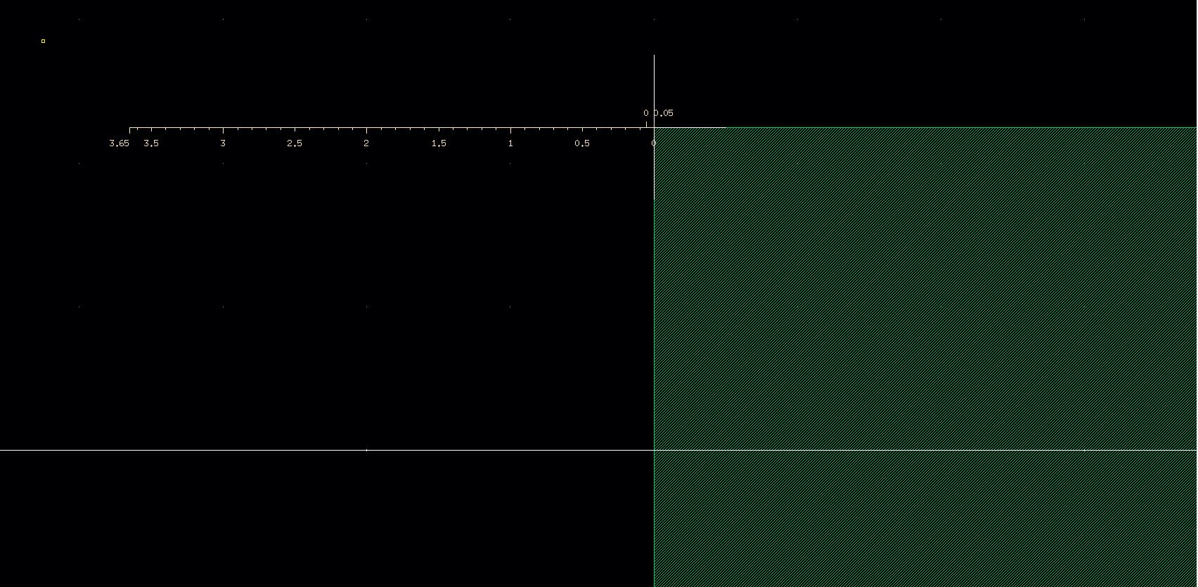
We will notice that there are markers on the edge, indicating an issue. The problem is that the edges are slightly off as shown here

http://cmosedu.com/jbaker/courses/ee421L/f17/students/escoba3/Lab3/Ruler.JPG

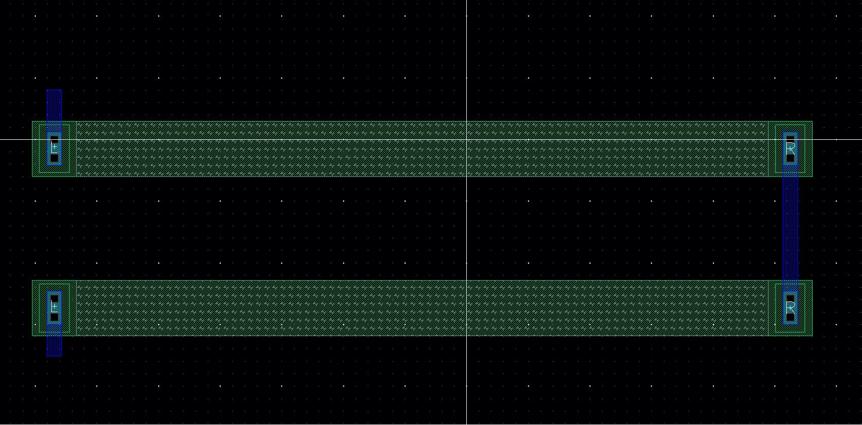
Once this was remedied, we added our N taps to the resistor to create the following

http://cmosedu.com/jbaker/courses/ee421L/f17/students/escoba3/Lab3/N_Well%20with%20N_Tap.JPG


By adding some pins to this, we can create something that looks like the following;

http://cmosedu.com/jbaker/courses/ee421L/f17/students/escoba3/Lab3/N_Well%20with%20L,R%20pins.JPG

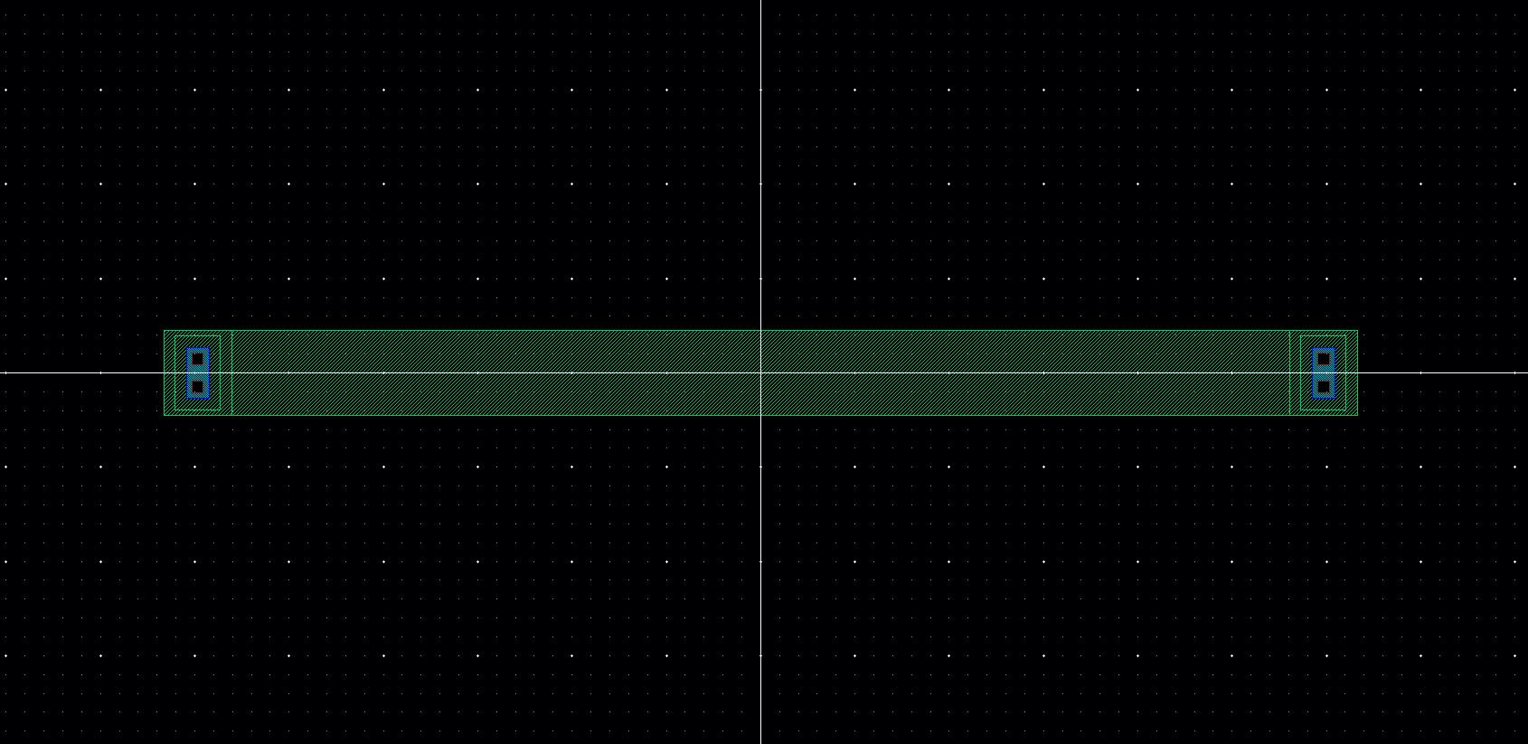
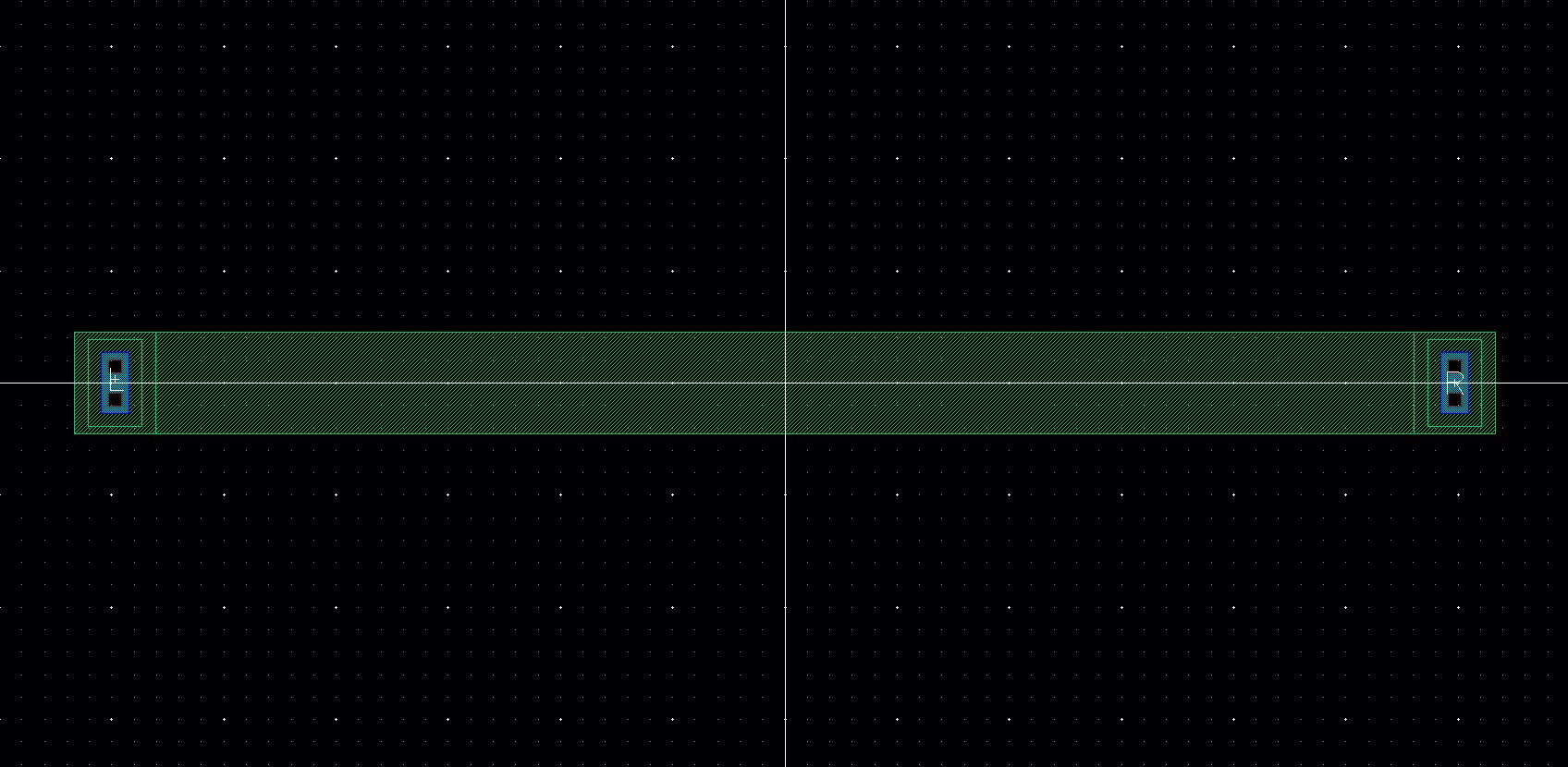
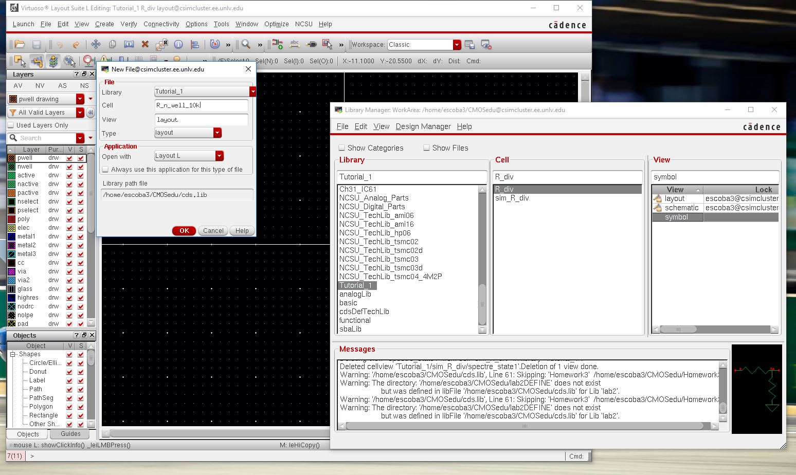
Now we are ready to add the metal layers, pins, and create another N_well to replicate our orginal circuit. 

http://cmosedu.com/jbaker/courses/ee421L/f17/students/escoba3/Lab3/2%20N_well's%20with%20pins.JPG

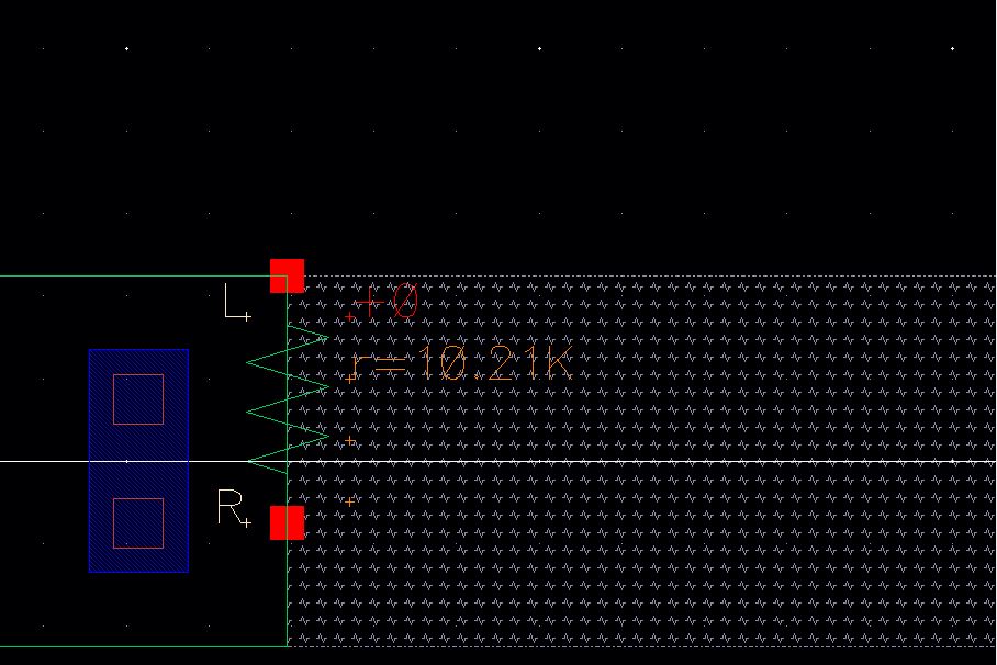
If we extract the N_well's, we can find out how much resistance we have created, in our case, we created a 10.21k resistor

http://cmosedu.com/jbaker/courses/ee421L/f17/students/escoba3/Lab3/extracted,%2010.21k.JPG

Link to download my simulations

Return to Listing