Project – Detector Circuit
nelsoz1@unlv.nevada.edu
For this
project we needed to design a circuit that could detect a specific sequence of
numbers.
Sequence: 101011
The first step
in designing this detector circuit was designing the D-Flip Flop component of
the circuit.
I started off
by creating the a transmission gate using a 6u/0.6u
PMOS and NMOS. This Transmission Gate is used alongside inverters to build a
D-Flip Flop.
For my
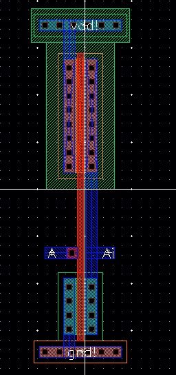
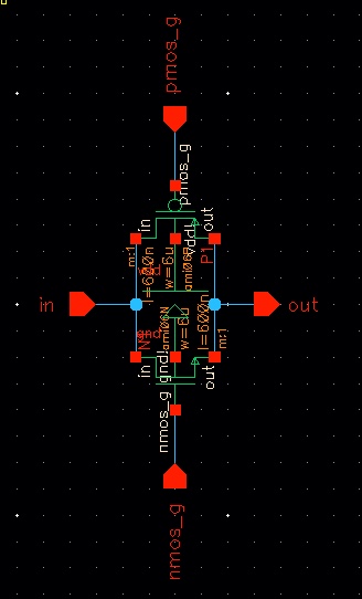
inverter I used the 6u/6u Inverter used in Lab 7.
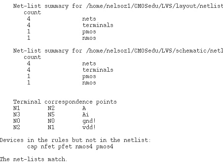
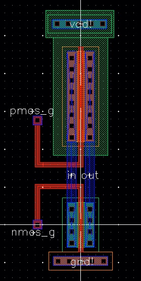
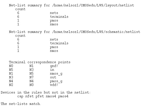
I went on to layout my inverter as well

After designing these I went on to build my D Flip Flop from Figure 13.22 in the textbook and created a symbol for it.
To ensure that
my design worked I needed to test my D Flip Flop.
To make it easier I created a Transmission gate symbol and implemented it in the D-Flip Flop

I then instantiated the Transmission Gate into my D Flip Flop Design
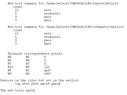
Now that I had a proper operating D Flip Flop I went to layout the D Flip Flop

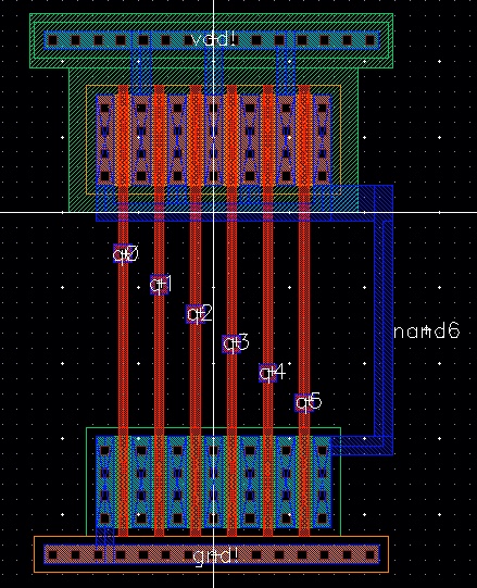
I needed to construct a 6 input NAND gate to
determine if the input is correct or incorrect. I created the schematic and
symbol for it.
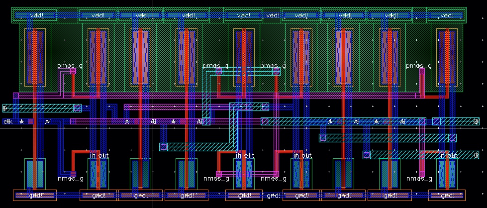
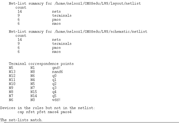
I then went on to layout the NAND gate

Now that I
have all components necessary to build my detection circuit, I can move on to
designing it.
I ran a
simulation to confirm that the Detector did in fact detect the proper sequence.
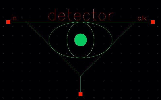
I also built a symbol for the schematic (An eye is appropriate because the detector can see allllllll the input)
After building the schematic I went on to layout the detector
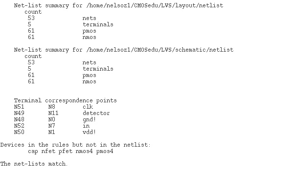
It passed DRC and LVS

I also simulated my extracted layout of the detector to ensure proper operation
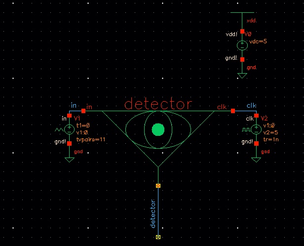
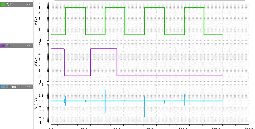
First I simulated a correct input, there is a small glitch but I believe that to be due to previous state input
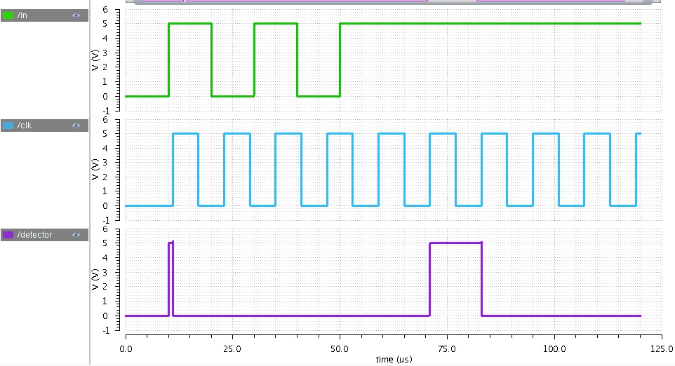
I also simulated incorrect input.
I linked my
detector library below.
