| Images | Description |
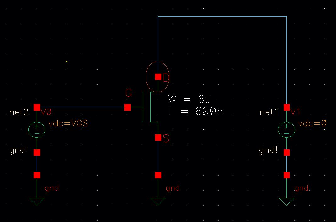
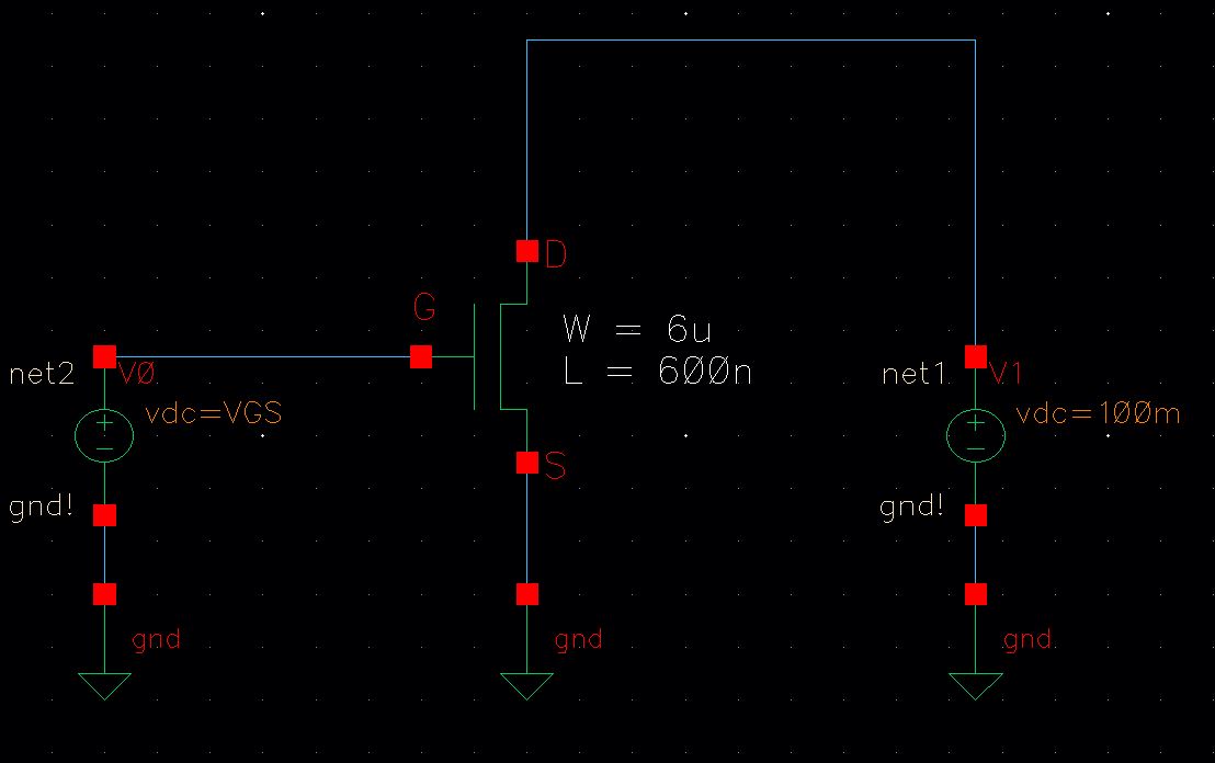
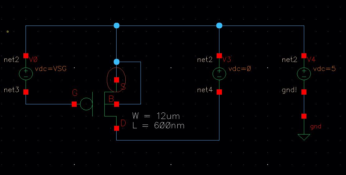
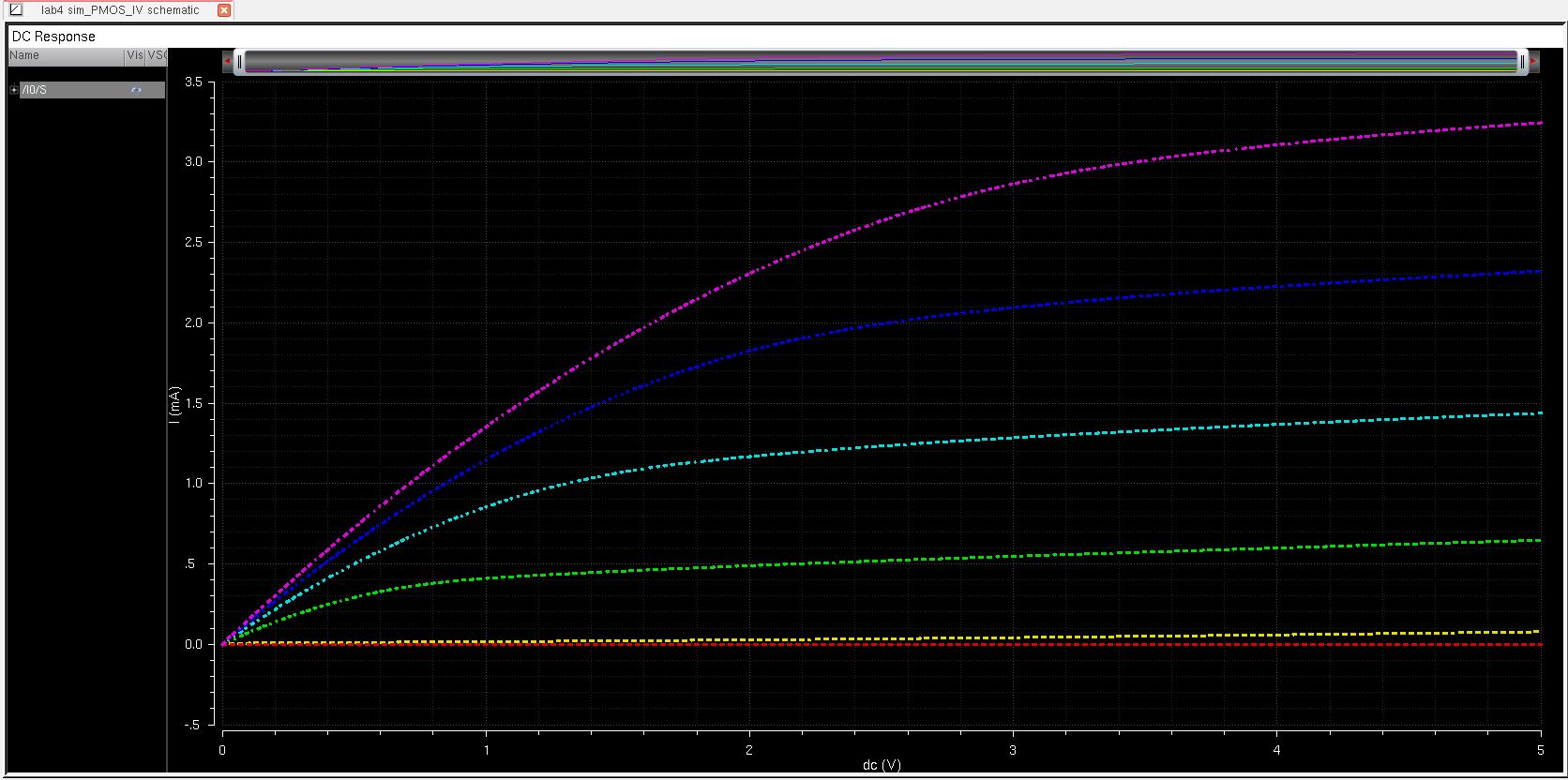
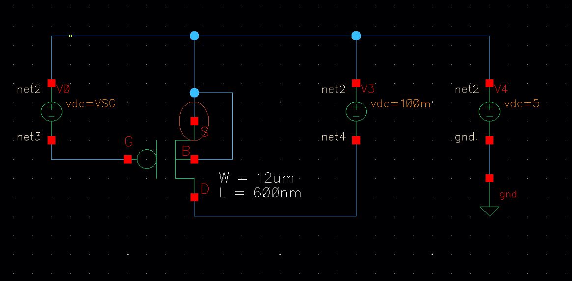
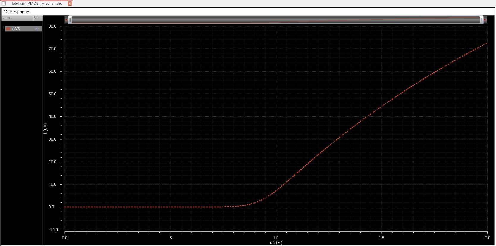
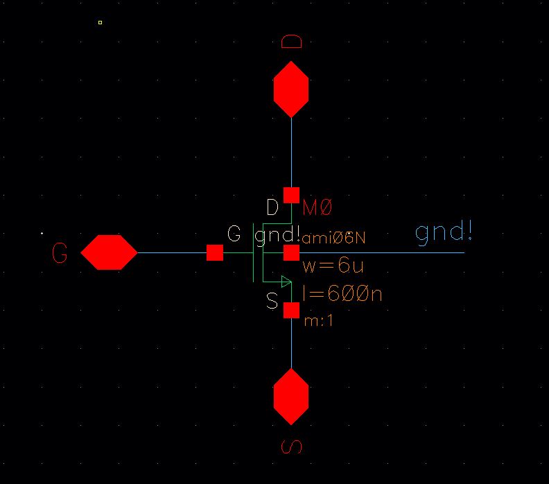
| PMOS_IV Schematic | 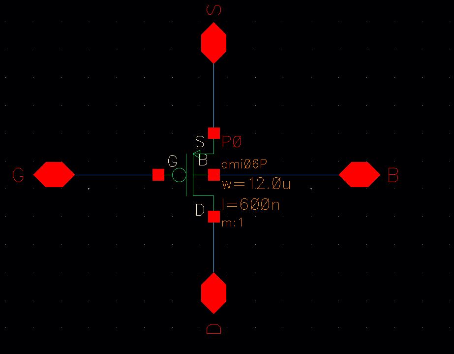 | - This is the schematic for the PMOS_IV
|
| Symbol | 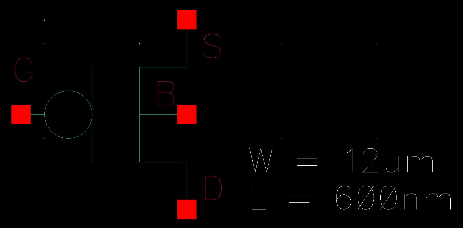 | - This is the symbol I created from the PMOS_IV schematic
|
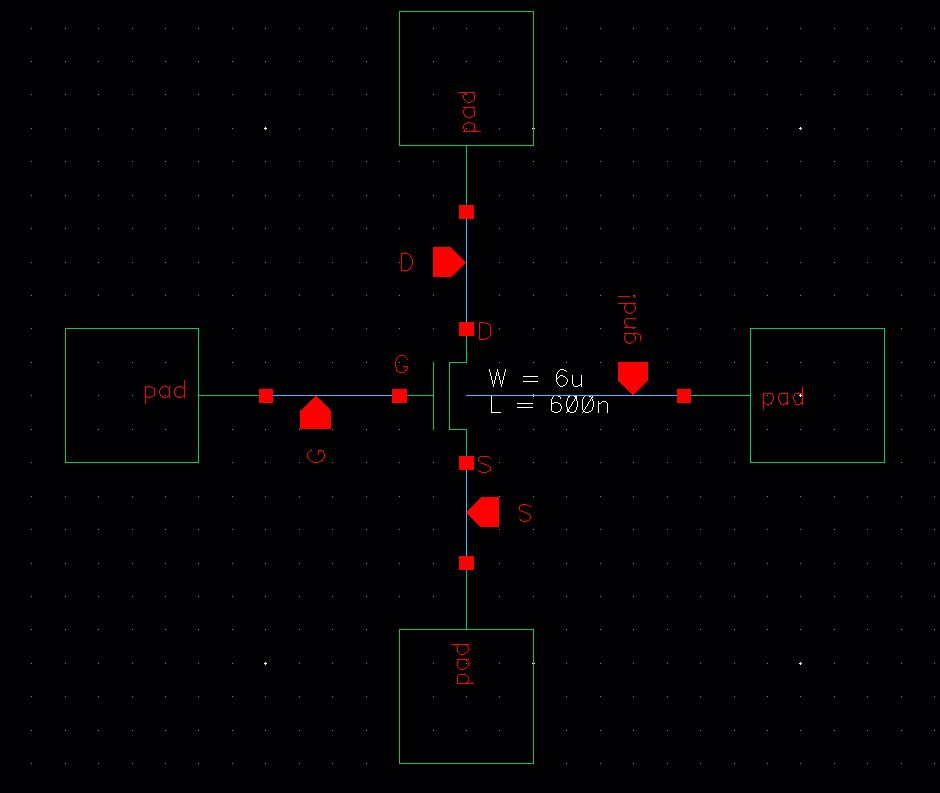
| PMOS Pad Schematic | 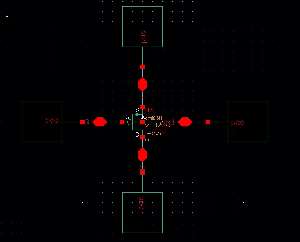 | - The schematic for the PMOS is similar to the NMOS. All that needed to be swapped was the NMOS and the schematic was complete
|
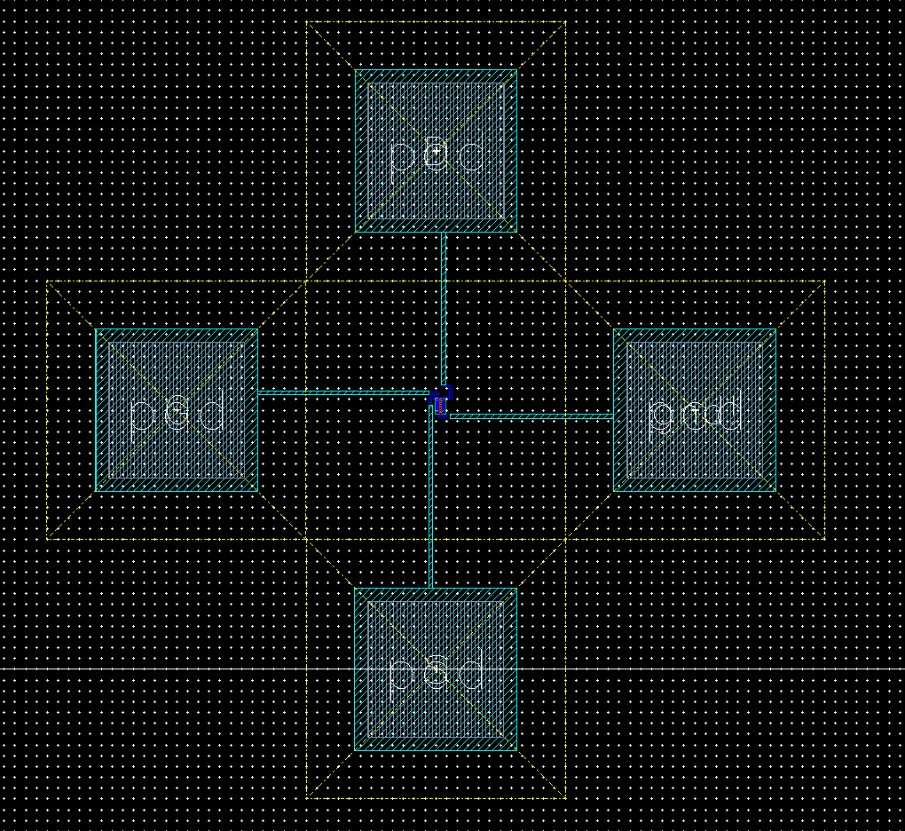
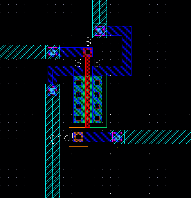
| Layout | 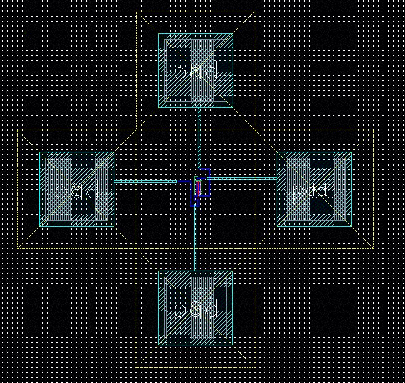 | - Similarly with the layout I had to swap out the NMOS with a PMOS layout and reconnected the wires
|
| Layout Zoomed | 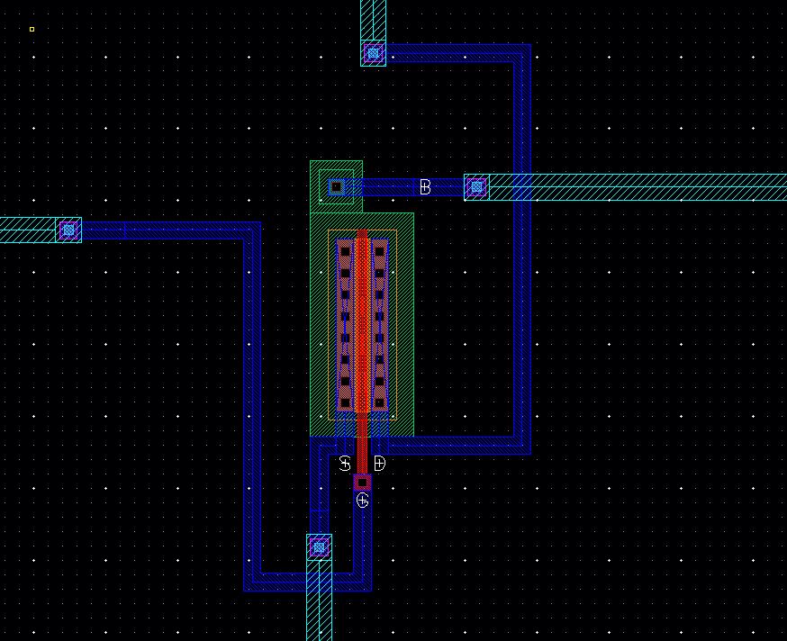 | - This is a zoomed in image of the layout with the PMOS in the center
|
| DRC & LVS | 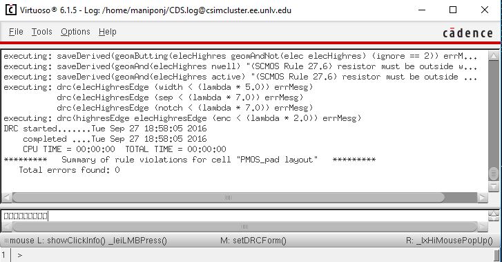
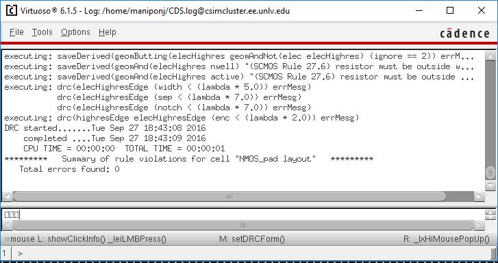
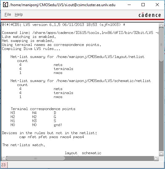
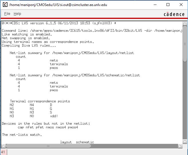 | - Once
I had both the layout and schematics completed, I ran a DRC for the
layout and ran an LVS for the extracted and schematic views.
|
