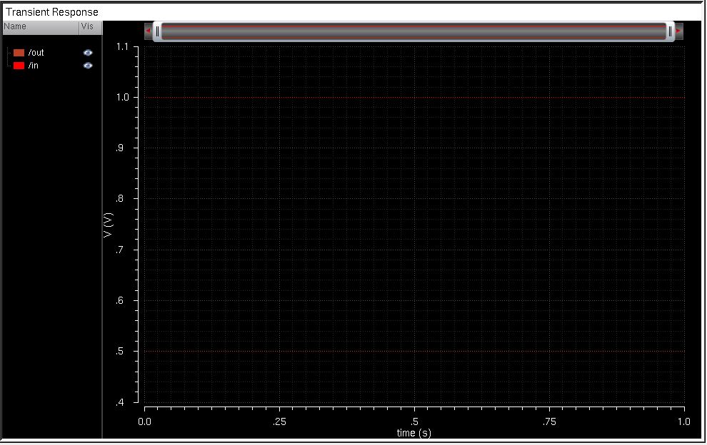
This first picture is the picture of the plotted input and output signals from the circuit we built in virtuoso. (the actual plots are a little bit hard to see because of the color and thickness of the lines, however, I will fix this for the next lab).
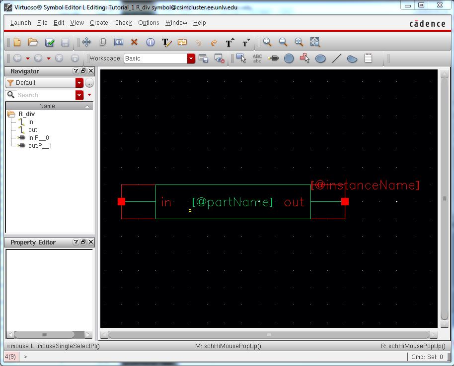
This picture is not a necessary picture because I realized it wasn't required after getting to this point in the tutorial and taking a screenshot of it. However, I thought I would include it anyways since it did the work for it.
The next two pictures are of my zip file that I emailed to myself as well as the contents inside.