Lab 3 - EE 421L
Brandon Thomas (email:thomasb3@unlv.nevada.edu)
Goal: The goal of this lab was to turn the 10-bit DAC from last weeks lab into a layout format using the n-well resistors created in Tutorial 1.
Procedures: The first thing we had to do was create the single 10k n-well resistor which was already created
in Tutorial 1. From here we had to use the resistor to create a
1-bit DAC be hooking up multiple resistors in the correct way, using
metal 1 as the connection from one to the other. The 1-bit DAC
was then used as a building block in the construction of the 10-bit, which was then extracted and simulated to see if the results came out to be the same as the schematic 10-bit DAC from last week's lab.
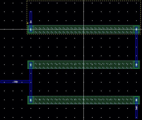
The 1-bit DAC was constructed using the 10k n-well resistor in the following manner:
After
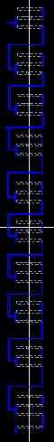
the construction of the 1-bit DAC, the 10-bit was created by laying out
10of the 1-bits which were each connected in the appropriate way by
metal1, which produced the following layout:
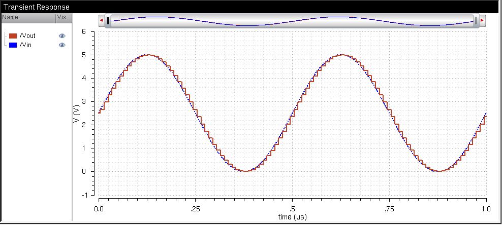
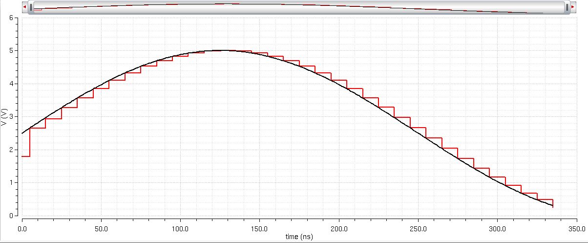
The following simulations were obtained:
After
completing the lab, I backed up my work by zipping the file where
everything for lab 3 was located and emailed the zipped folder to
myself.