Lab 1 - ECE 421L 

Authored by Stephanie Silic,

August 29th, 2015 


Lab Report
 

The goal of this lab was to learn how to set up properly and get familiar with using Cadence Virtuoso design studio by going through the first part of the Cadence Tutorial 1 found on cmosedu.com. 


Part 1: Cadence Tutorial


The first few steps in the tutorial involved setting up the Cadence design studio properly.

To do this, we had to do several things before we can start using Cadence. First, we needed the Cadence Design Kit from NCSU.edu


                                                                  http://cmosedu.com/jbaker/courses/ee421L/f15/students/silics/Lab1/Tutorial_1%20NCSU%20design%20kit.JPG

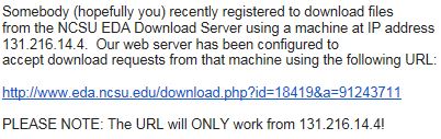
To get the kit, I requested the url and was sent an email from ncsu with a specific url to the downloadable kit;


                                                       http://cmosedu.com/jbaker/courses/ee421L/f15/students/silics/Lab1/Tutorial1_NCSUemail.jpg

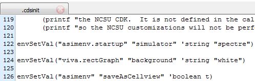
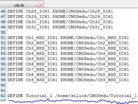
Once this kit was extracted, it needed to be copied into my home directory in MobaXterm. Next, we needed to modify some basic things. First, we had to change the names cdsinit, simrc, and cdsenv by adding a period in front of them. Also we were to add to the .cdsinit file certain customizations such as using spectre for the default schematic editor and changing the plot background to white. These modifications are shown below:


                                                  http://cmosedu.com/jbaker/courses/ee421L/f15/students/silics/Lab1/cdsinit_modifications.JPG


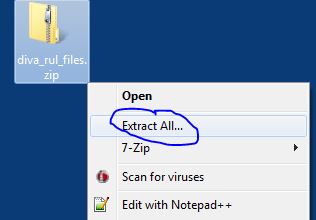
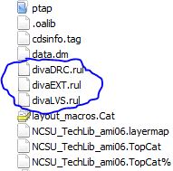
And finally we needed to fix the tech library in ncsu-cdk-1.6.0.beta by deleting the 'bugged' files divaDRC.rul, divaEXT.rul, and divaLVS.rul, and copy the fixed diva_rul_files intothe same library.


                                                  http://cmosedu.com/jbaker/courses/ee421L/f15/students/silics/Lab1/Tutorial1_extracting%20diva_rul%20zip.jpg   http://cmosedu.com/jbaker/courses/ee421L/f15/students/silics/Lab1/Tutorial1_divafiles.JPG

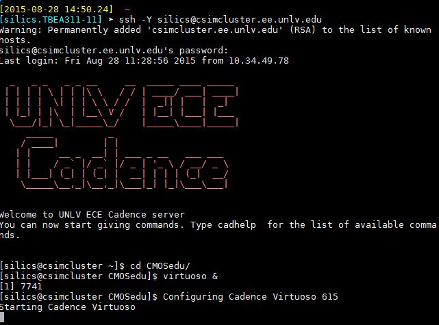
Finally, we are ready to start Cadence:


                                                   http://cmosedu.com/jbaker/courses/ee421L/f15/students/silics/Lab1/Tutorial1_Cacence.jpg  

For this next part of the tutorial, we were to create a basic circuit using the schematic editor and simulate it.

First, we needed to create a new library called "Tutorial 1" in the Library Manager window:


http://cmosedu.com/jbaker/courses/ee421L/f15/students/silics/Lab1/Tutorial1_creating%20library.jpg  http://cmosedu.com/jbaker/courses/ee421L/f15/students/silics/Lab1/Tutorial1_Define%20Tutorial1.JPG


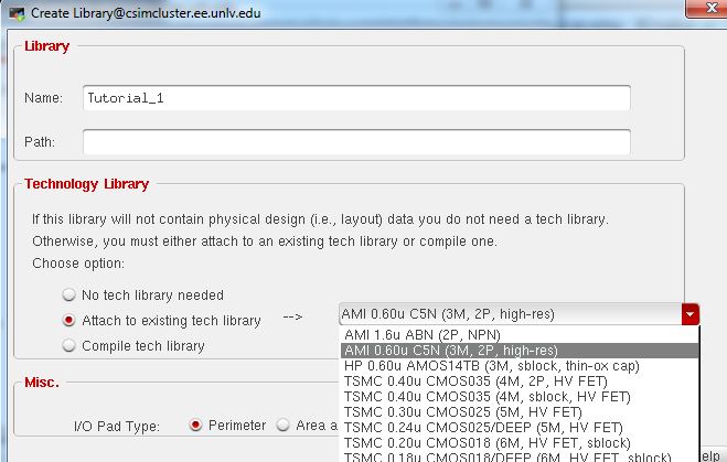
For this library, we needed to ensure it was attached to the tech library shown.


Next, we add a cell by clicking File -> New -> Cell View and create a schematic named R_div


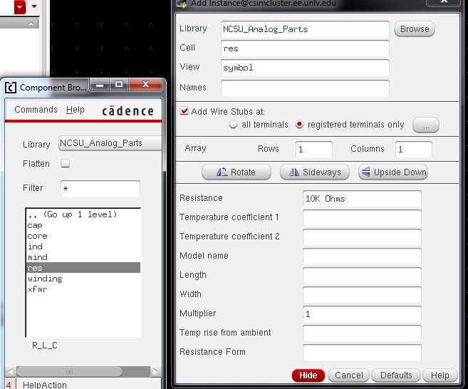
In the schematic editor window, we can begin to create the circuit by clicking Create -> New Instance (or hitting the 'i' key) and selecting R_L_C from the components library, then 'res' for resistor, and set the resistor value to 10k Ohms before putting the resistor down.


                                        http://cmosedu.com/jbaker/courses/ee421L/f15/students/silics/Lab1/Tutorial1_10kohm_box.jpg


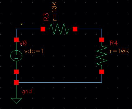
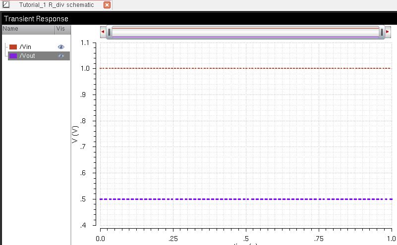
Next we add a voltage source, draw wires connecting each component, and the circuit is complete and ready for simulation:

                                                        http://cmosedu.com/jbaker/courses/ee421L/f15/students/silics/Lab1/Tutorial1_circuitwithwires.jpg


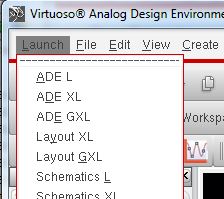
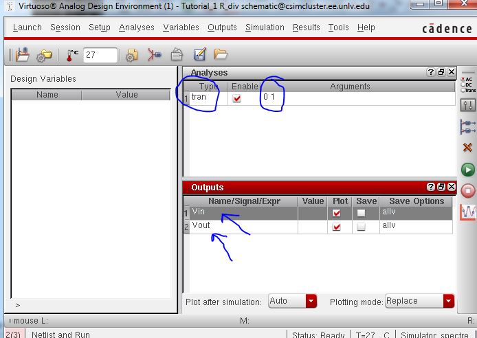
Since we are ready to simulate, we select Launch -> ADE L:        


                                                                        http://cmosedu.com/jbaker/courses/ee421L/f15/students/silics/Lab1/Tutorial1_launchADE.jpg

Now in this window we set up the simulation parameters: we wanted a transient analysis for 1 second; this is done from the tab Analyses -> Choose.
Setting Vin and Vout to be plotted is achieved by selecting Outputs -> To Be Plotted (as shown).
After this is done, the Analog Design Environment window looks like this:
 
         http://cmosedu.com/jbaker/courses/ee421L/f15/students/silics/Lab1/Tutorial1_tran_proof.jpg        http://cmosedu.com/jbaker/courses/ee421L/f15/students/silics/Lab1/Tutorial1_tobeplotted.jpg

And finally, the we hit the green arrow button and see the simulation!


                       http://cmosedu.com/jbaker/courses/ee421L/f15/students/silics/Lab1/Tutorial1_simulation.jpg


 Part 2: Backup Method


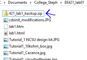
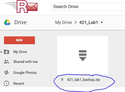
I backed up this lab report by putting the .html file and all the snips into a zipped folder and uploading that to my Google Drive. The following images show the zipped folder on my desktop and in Drive:

 http://cmosedu.com/jbaker/courses/ee421L/f15/students/silics/Lab1/bckup1.JPG     http://cmosedu.com/jbaker/courses/ee421L/f15/students/silics/Lab1/bckup2.JPG


return to my lab reports