Lab Project - EE421L
Authored
by Russ Prado,
prador@unlv.nevada.edu
11/9/2015
Lab Report:
First half of the Project:
- Design an 8-Bit resettable (input "clear") Up/Down Counter
Transmission Gates used in D-Flip Flop:25k-1k_Res_voltage-divider

D-Flip Flop with clearhttp://cmosedu.com/jbaker/courses/ee421L/f15/students/prador/:
 25k-1k_Res_voltage-divider
8-Bit Resettable UP/DOWN Counter:
Here
I used a 2-1 MUX on each bit to control whether the counter will be
counting up or down. When High is tied to the Up-Down terminal, it will
count up, while a low input will allow for it to count down.


Simulations:

Up-Count:

Down Count:

Set:

Reset:

Set+Reset:
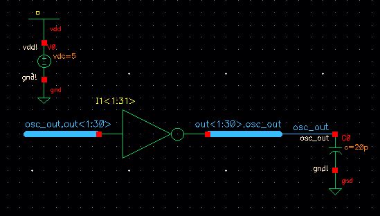
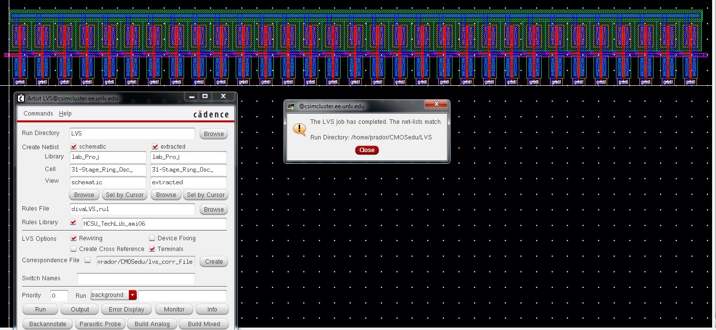
- 31-Stage Ring Oscillator with a buffer for driving a 20pF off-chop load


- NAND and NOR gates using 6u.6u NMOSs and PMOSs
NAND Gate:


Simulation:


NOR Gate:
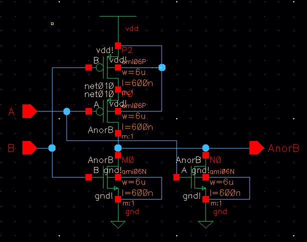

Simulation:


- An Inverter made with a 6u/.6u NMOS and 12u/.6u PMOS


- Transistors, both PMOS and NMOS, measuring 6u/.6u where all 4 termainsl of each device are connected to bond pads
NMOS:


PMOS:


- Using
the 25k resistor laid out velow and a 10k resistor implement implement
a voltage divider (need only 1 more pad above the ones used for the 25k
resistor)

______________________________________________________________________________________________
Part 2:
Here we will go through the verified layouts of the following:
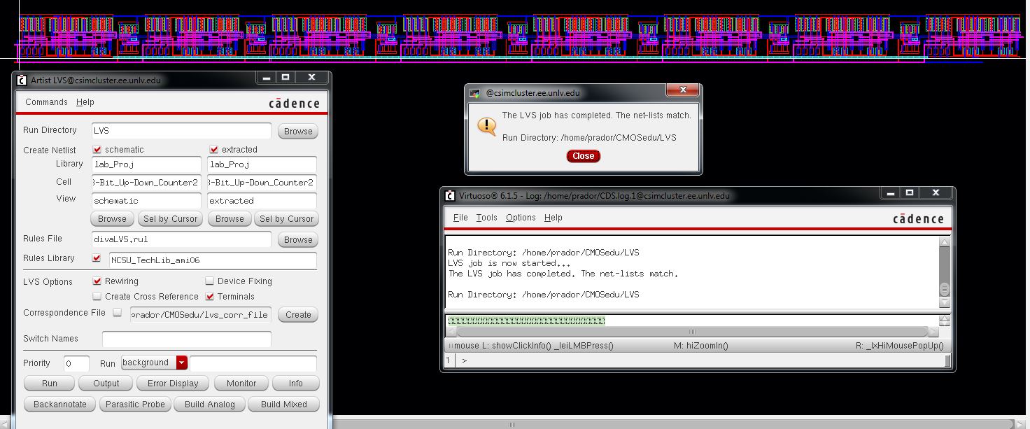
- 8-Bit Resettable (input "clear") Up-Down Counter
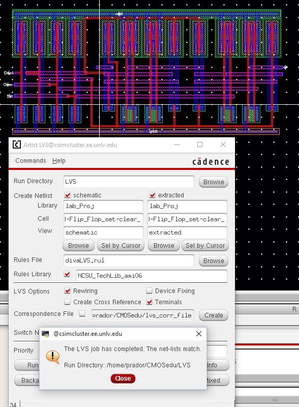
- D Flip-Flop with Set and Clear
- NAND Gate using 6/0.6 NMOSs and PMOSs

- NOR Gate using 6/0.6 NMOSs and PMOSs

- Inverter made with a 6/0.6 NMOS and a 12/0.6 PMOS

- Transisitors: NMOS and PMOS, both measuring 6u/0.6u


- Voltage Divider using the 25k Resistor laid out below and a 10k Resistor


Don't Forget to back up your files
proj.zip
Add
a return to the listing of your labs