Project - EE 421L
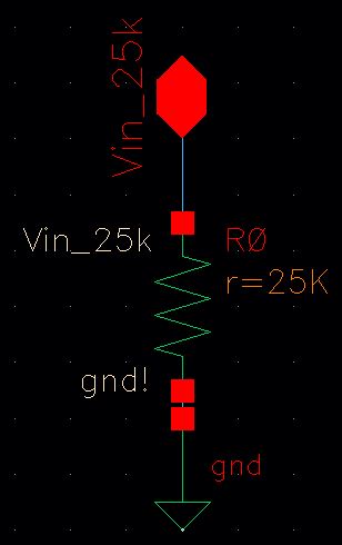
The image above shows the schematic of a resistor.
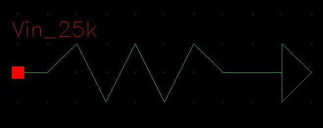
The image above shows the symbol.
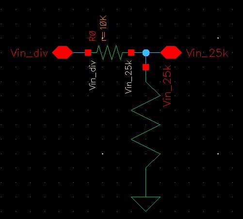
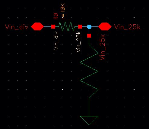
The image above shows the schematic of a voltage divider.
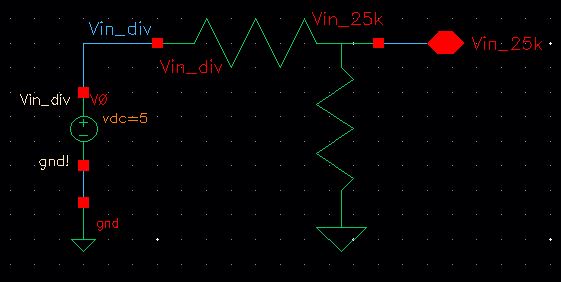
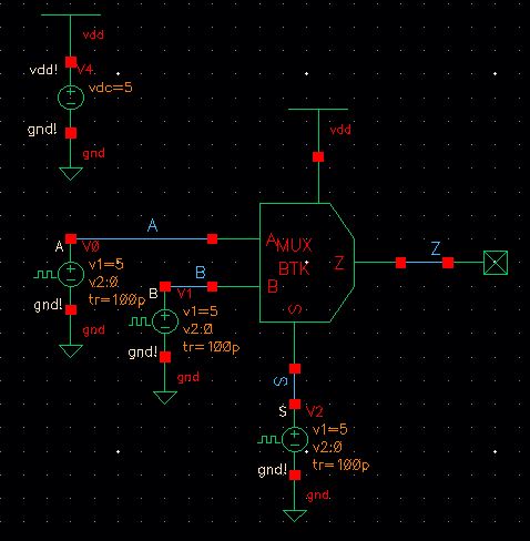
The image above shows the simulation schematic.
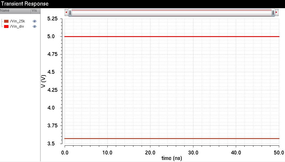
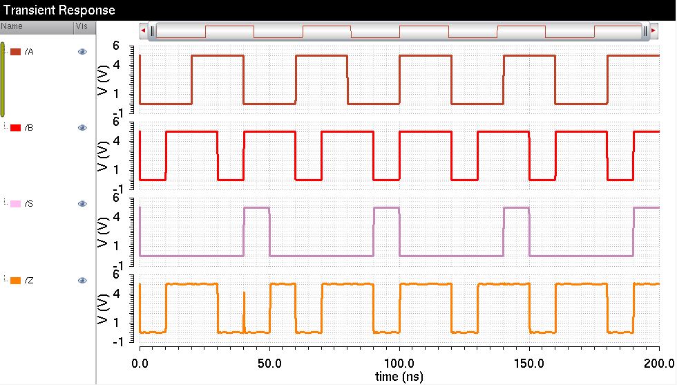
The image above shows the simulation results.
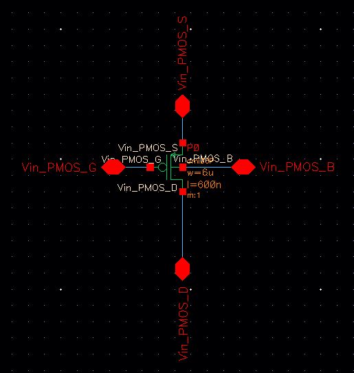
The image above shows the schematic of a PMOS.
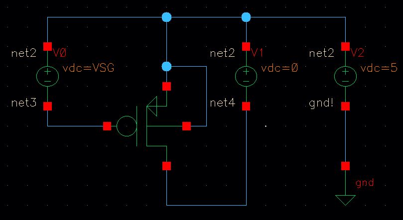
The image above shows the simulation schematic.
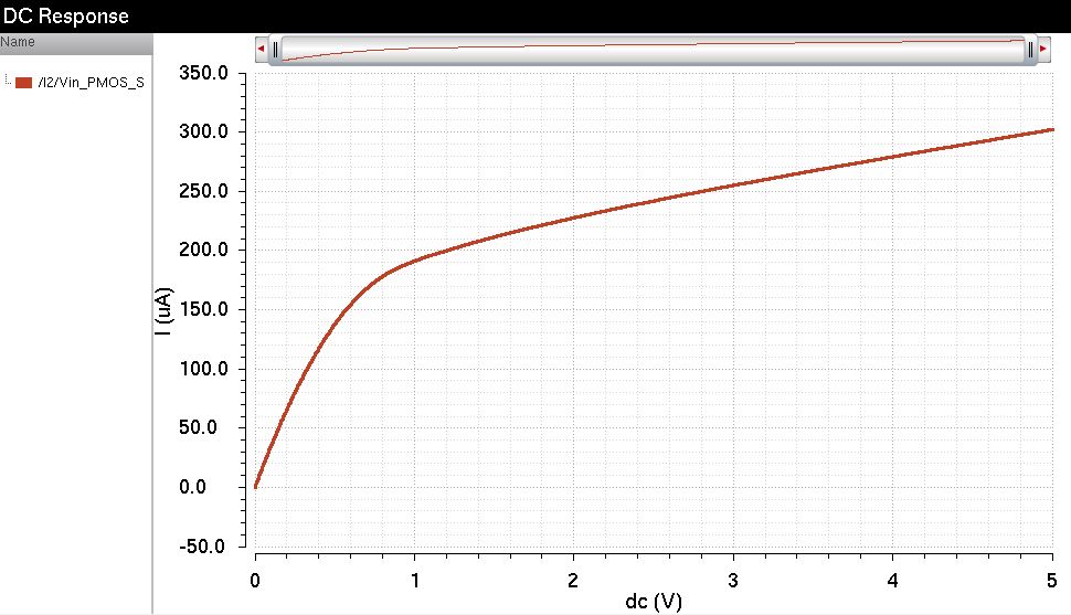
The image above shows the simulation results.
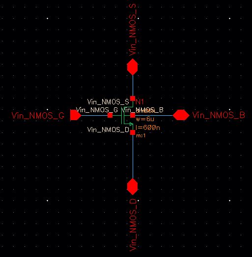
The image above shows the schematic of an NMOS.
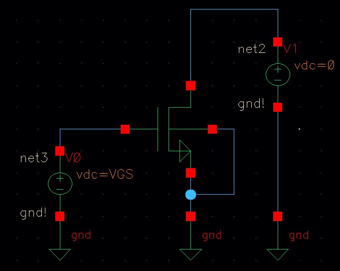
The image above shows the simulation schematic.
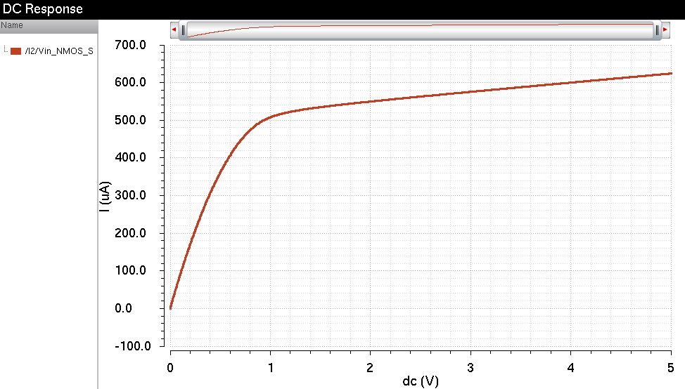
The image above shows the simulation results.
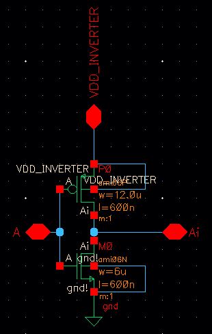
The image above shows the schematic of an inverter.
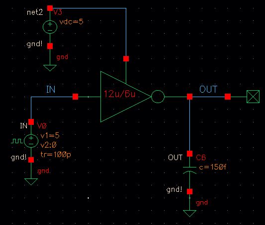
The image above shows the simulation schematic.
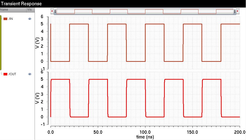
The image above shows the simulation results.
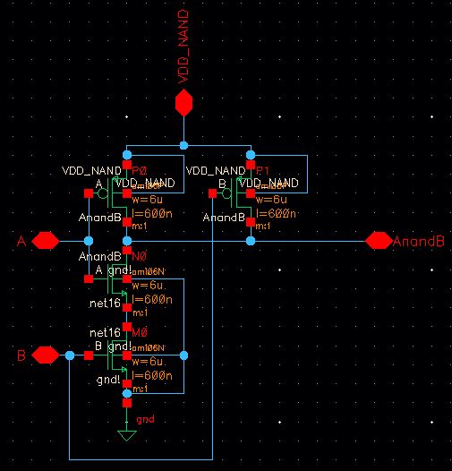
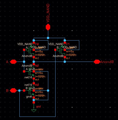
The image above shows the schematic of a NAND gate.
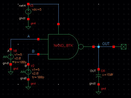
The image above shows the simulation results.
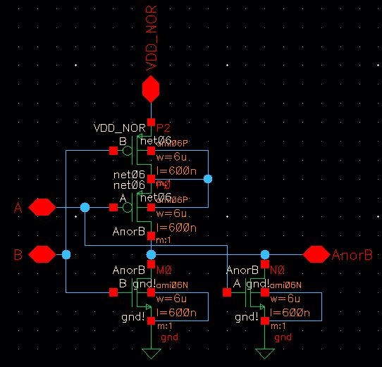
The image above shows the schematic of a NOR gate.
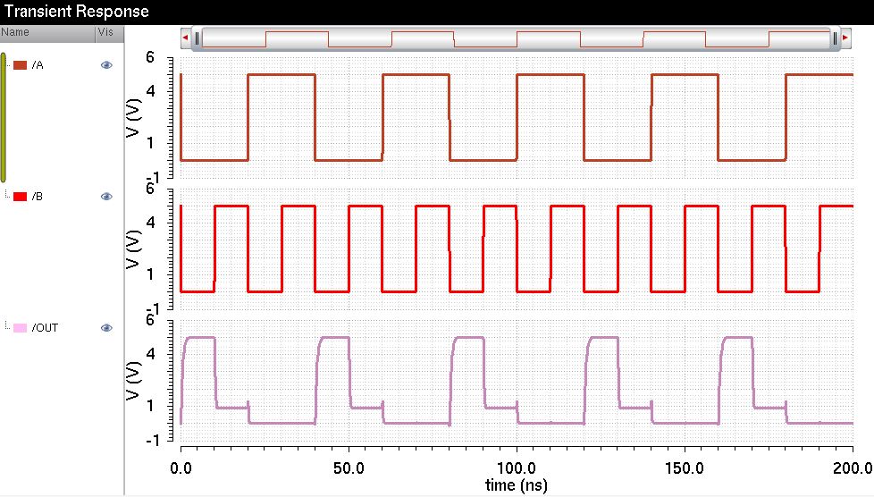
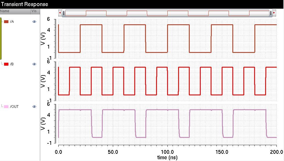
The image above shows the simulation results.
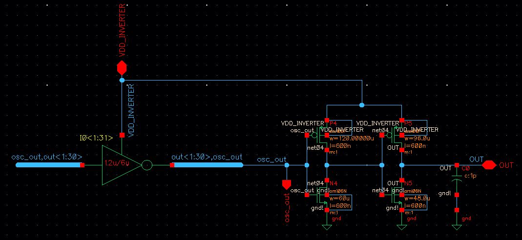
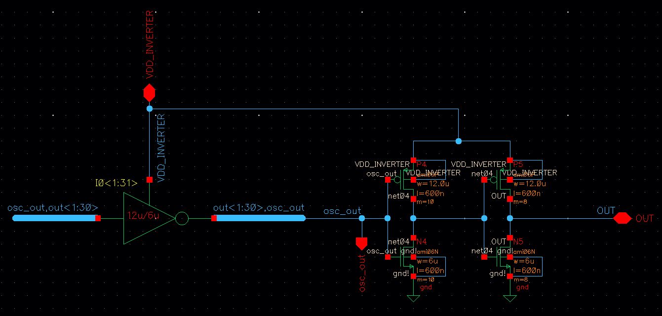
The image above shows the schematic of a ring oscillator.
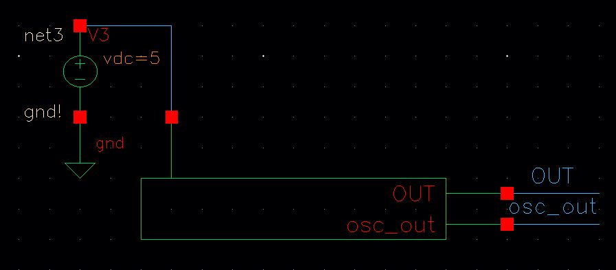
The image above shows the simulation schematic.
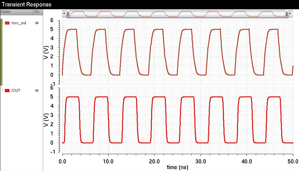
The image above shows the simulation results.
The image above shows the simulation schematic.
The image above shows the simulation results.
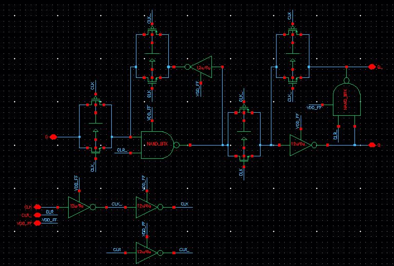
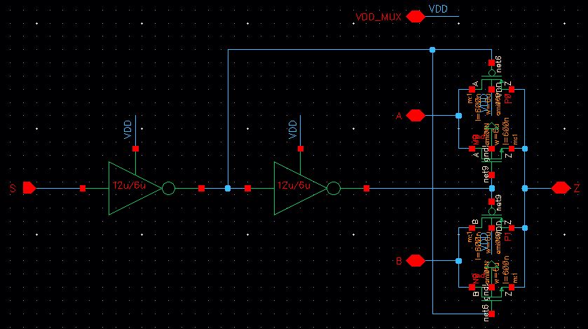
The image above shows the schematic of a D flip-flop.
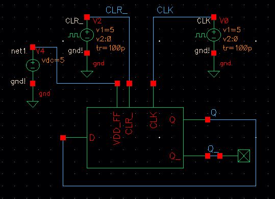
The image above shows the simulation schematic.
The image above shows the simulation results.
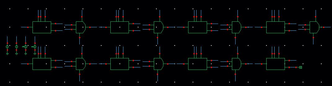
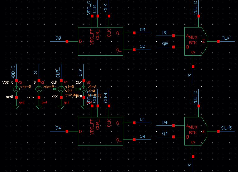
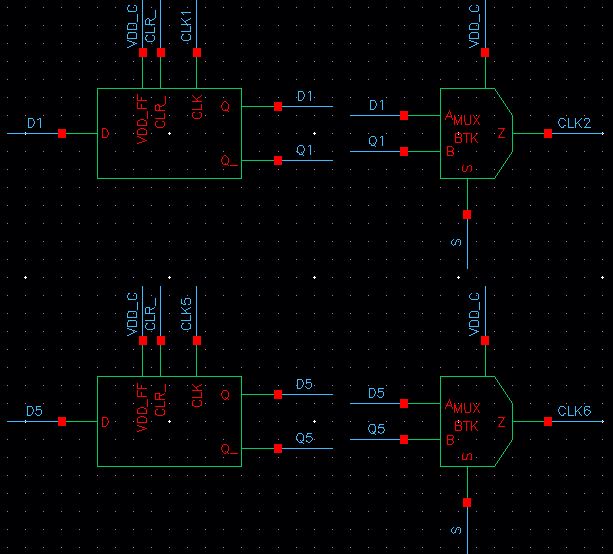
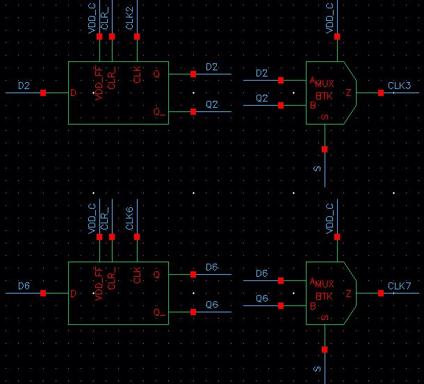
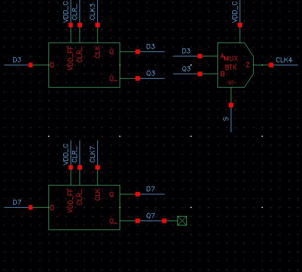
The image above shows the schematic of a counter.
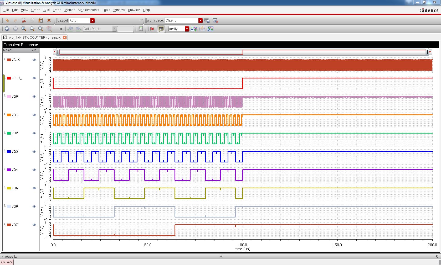
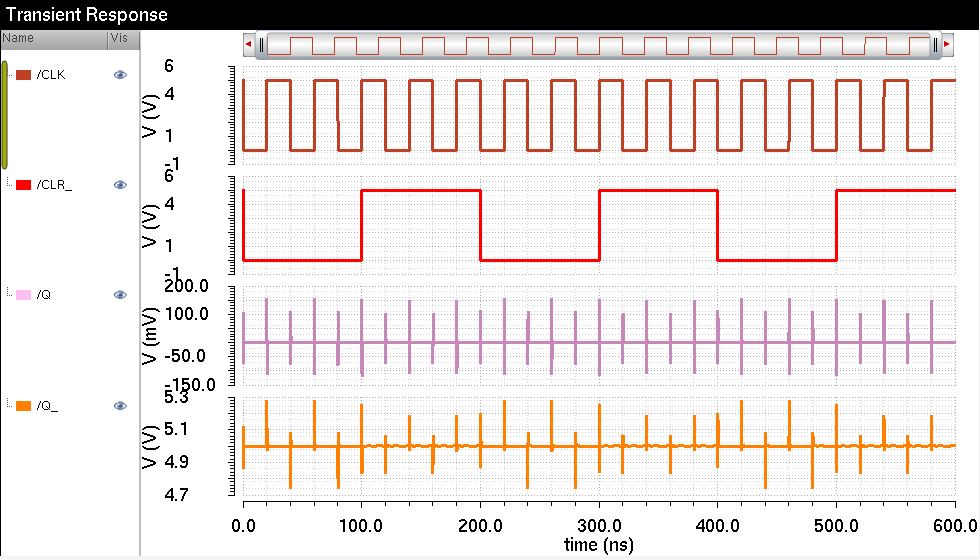
The image above shows the simulation results.
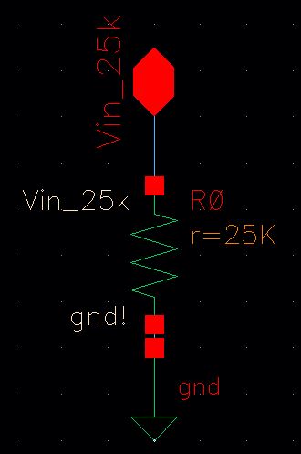
The image above shows the schematic of a resistor.

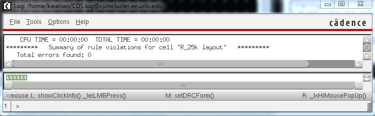
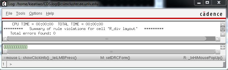
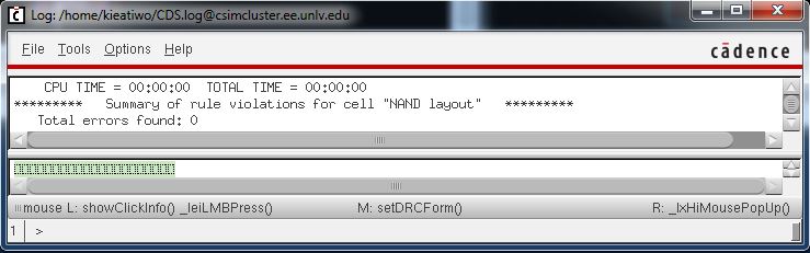
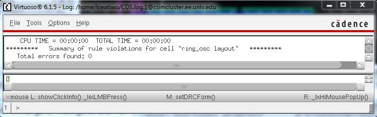
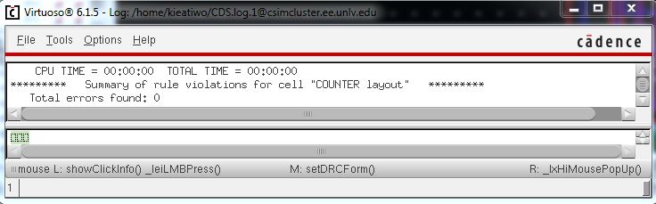
The image above shows the successful DRC.
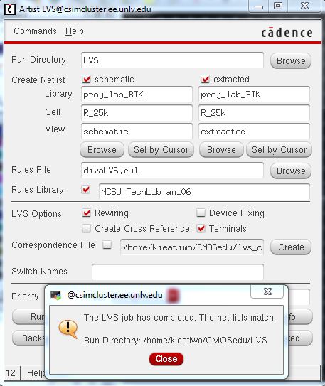
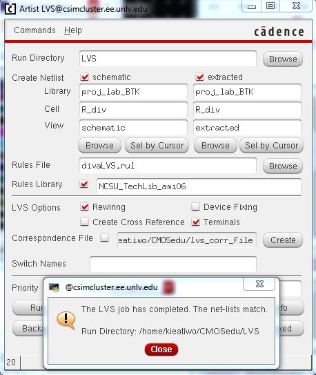
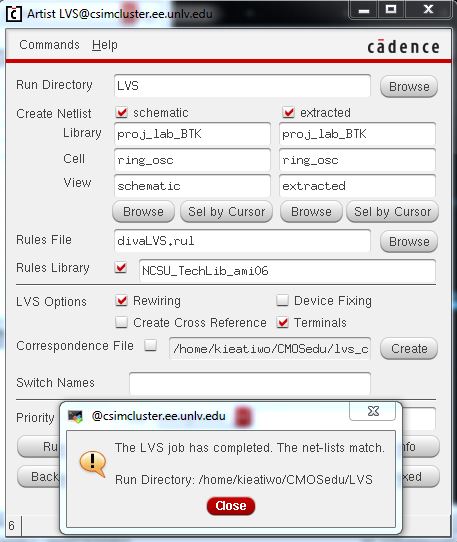
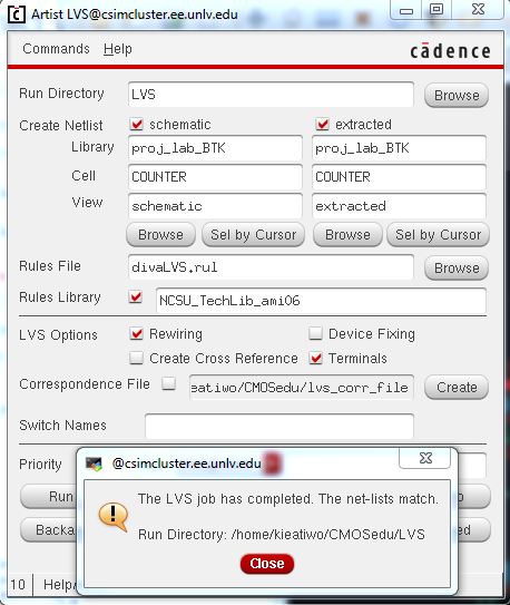
The image above shows the successful LVS.
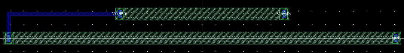
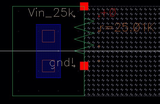
The image above shows the layout.
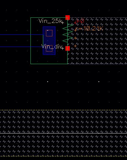
The image above shows the extracted layout.
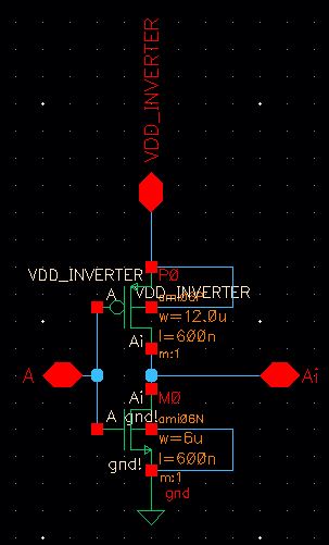
The image above shows the schematic of an inverter.
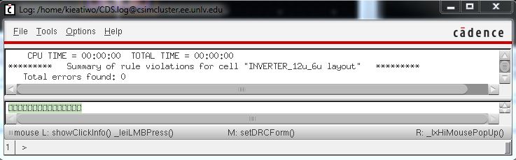
The image above shows the successful DRC.
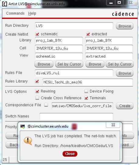
The image above shows the successful LVS.
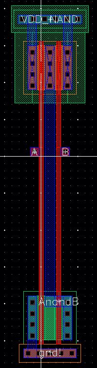
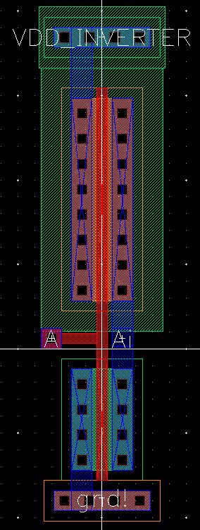
The image above shows the layout.
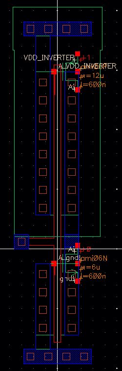
The image above shows the extracted layout.
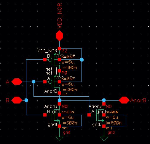
The image above shows the schematic of a NOR gate.
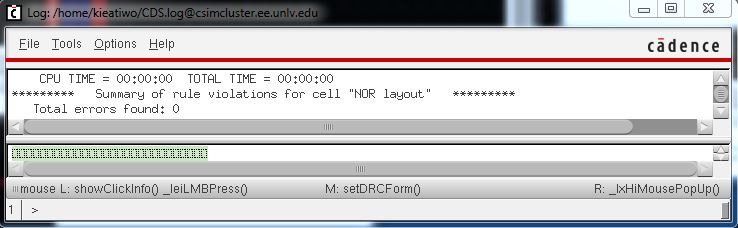
The image above shows the successful DRC.

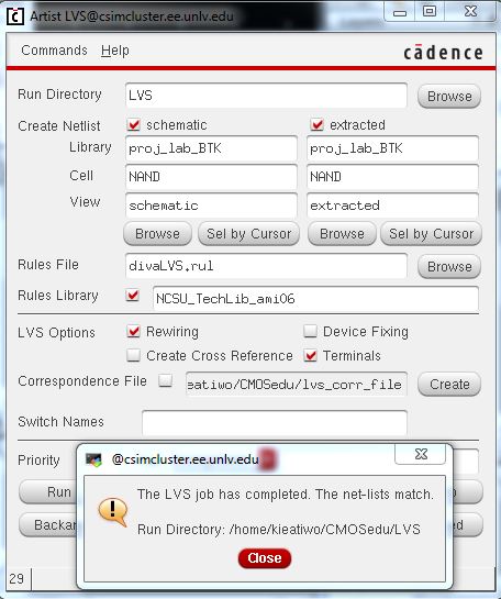
The image above shows the successful LVS.
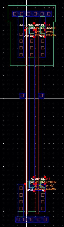
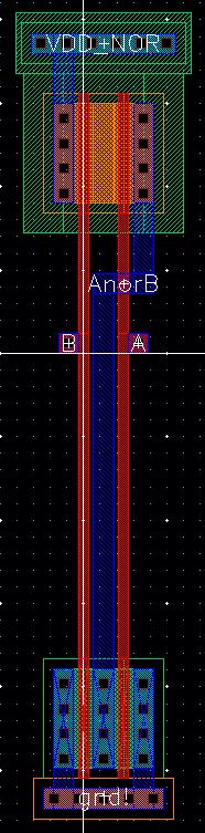
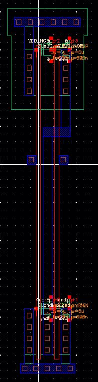
The image above shows the layout.
The image above shows the extracted layout.
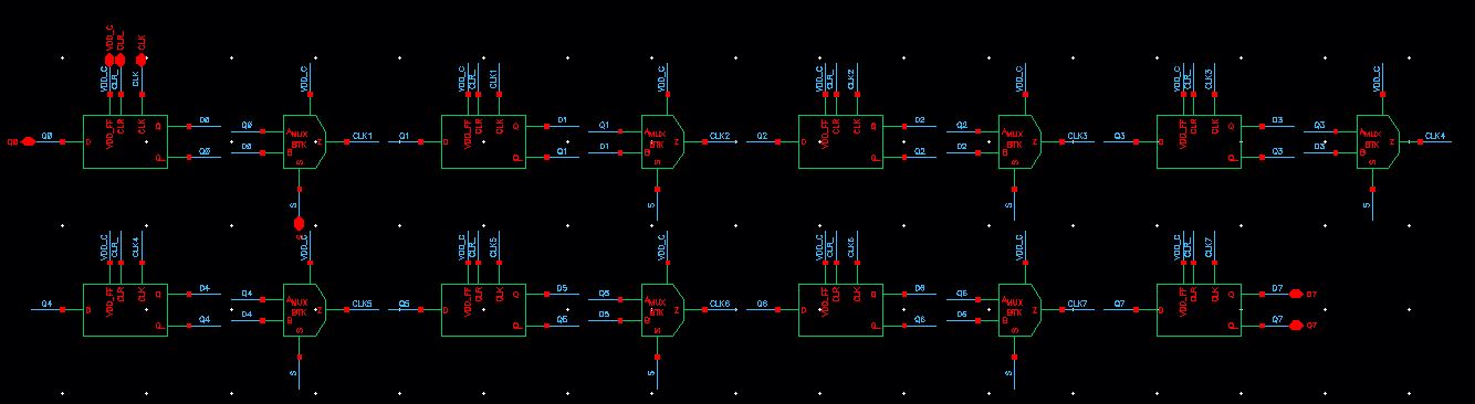
The image above shows the schematic of a counter.
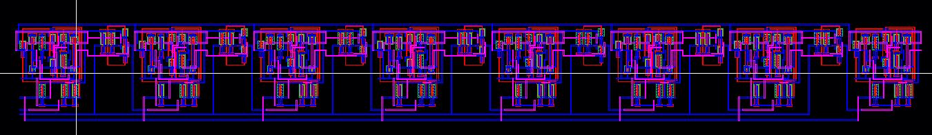
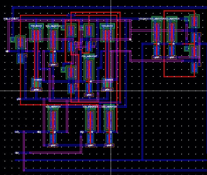
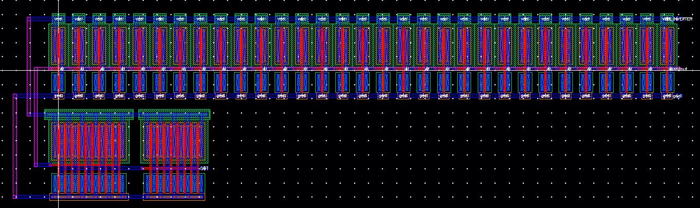
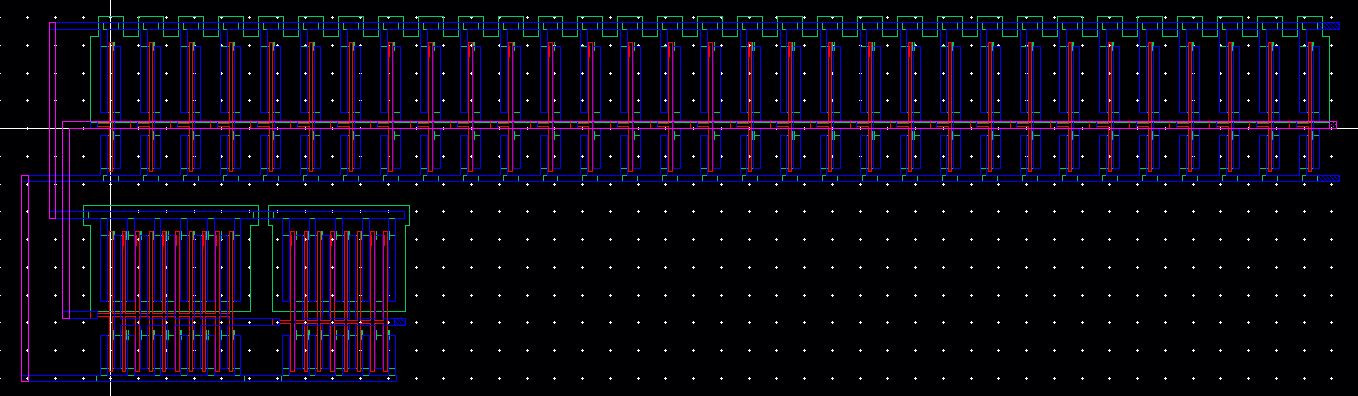
The image above shows the enlarged layout.
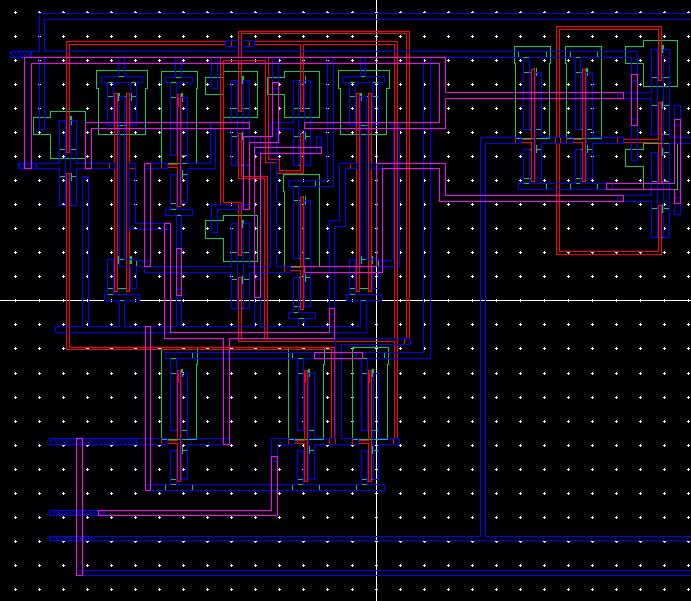
The image above shows the extracted layout.
To download the designs from this lab, click here