Lab 7 - EE 421L 

Authored by Brian Kieatiwong

kieatiwo@unlv.nevada.edu

10/03/15


This lab consists of the creation of the schematic, symbol, and simulation of an 8-bit NAND gate, NOR gate, AND gate, inverter, OR gate, and 2-to-1 DEMUX/MUX. This lab will also show the schematic, symbol, and layout of an 8-bit full adder. This lab will have the cells available for download and show the backing up of all lab work.


http://cmosedu.com/jbaker/courses/ee421L/f15/students/kieatiwo/Lab7/1.JPG

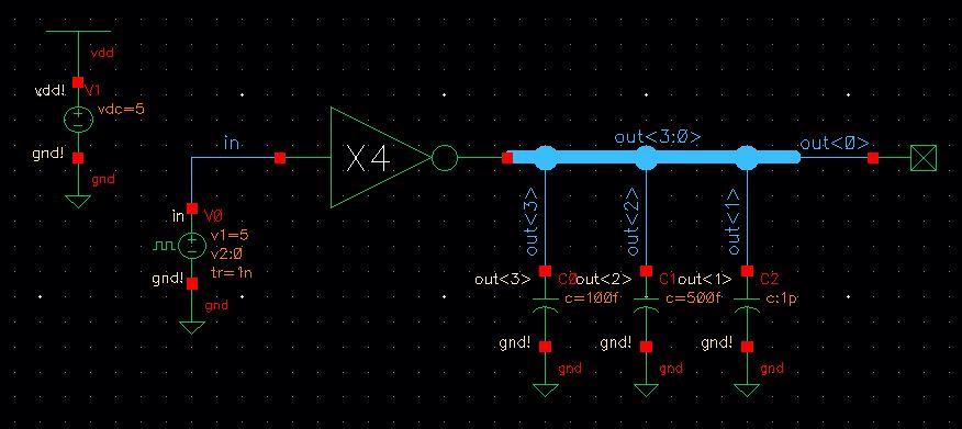
The image above shows the simulation schematic of a 4-bit inverter using 6u/0.6u MOSFETs.


http://cmosedu.com/jbaker/courses/ee421L/f15/students/kieatiwo/Lab7/2.JPG

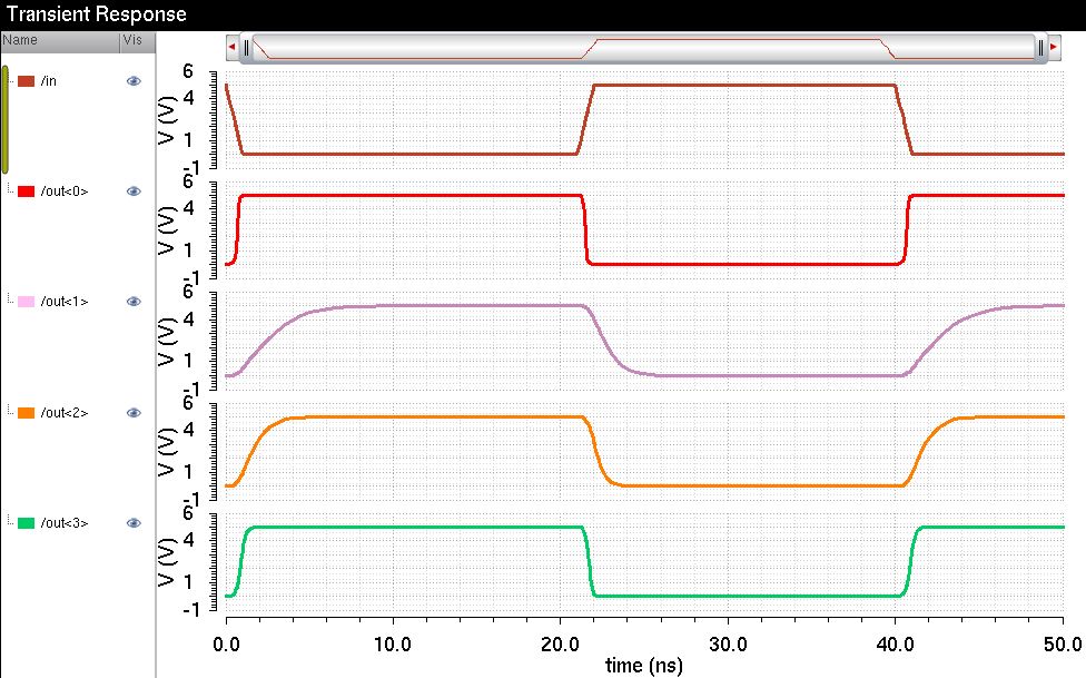
The image above shows the results of a 4-bit inverter using 6u/0.6u MOSFETs.


http://cmosedu.com/jbaker/courses/ee421L/f15/students/kieatiwo/Lab7/3.JPG

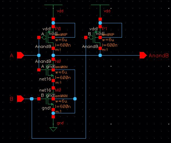
The image above shows the schematic of a NAND gate using 6u/0.6u MOSFETs.


 http://cmosedu.com/jbaker/courses/ee421L/f15/students/kieatiwo/Lab7/4.JPG

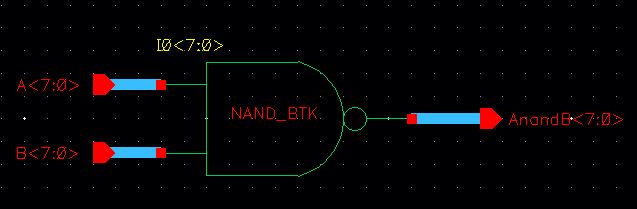
The image above shows the schematic of an 8-bit NAND gate using 6u/0.6u MOSFETs.


http://cmosedu.com/jbaker/courses/ee421L/f15/students/kieatiwo/Lab7/5.JPG

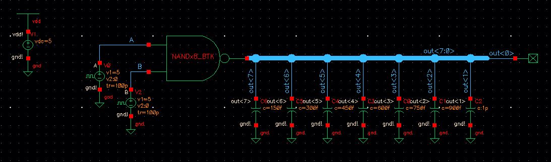
The image above shows the simulation schematic of an 8-bit NAND gate using 6u/0.6u MOSFETs.


http://cmosedu.com/jbaker/courses/ee421L/f15/students/kieatiwo/Lab7/6.JPG

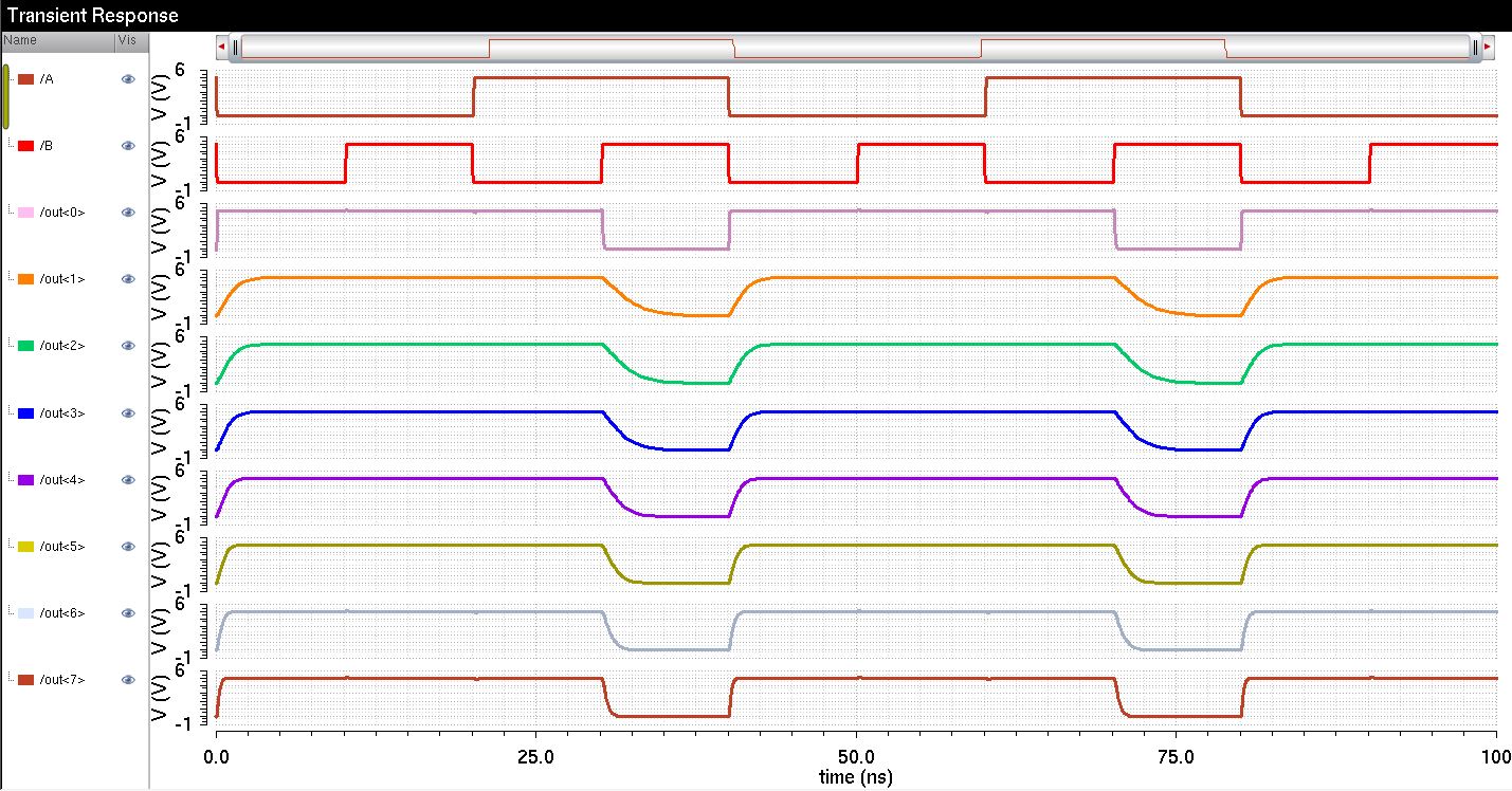
The image above shows the results of an 8-bit NAND gate using 6u/0.6u MOSFETs.


http://cmosedu.com/jbaker/courses/ee421L/f15/students/kieatiwo/Lab7/7.JPG

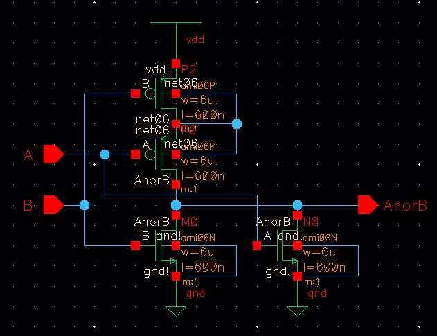
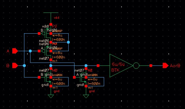
The image above shows the schematic of a NOR gate using 6u/0.6u MOSFETs.


http://cmosedu.com/jbaker/courses/ee421L/f15/students/kieatiwo/Lab7/8.JPG

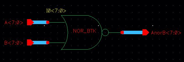
The image above shows the schematic of an 8-bit NOR gate using 6u/0.6u MOSFETs.


http://cmosedu.com/jbaker/courses/ee421L/f15/students/kieatiwo/Lab7/9.JPG

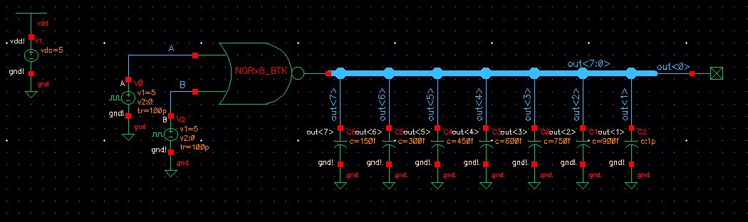
The image above shows the simulation schematic of an 8-bit NOR gate using 6u/0.6u MOSFETs.


http://cmosedu.com/jbaker/courses/ee421L/f15/students/kieatiwo/Lab7/10.JPG

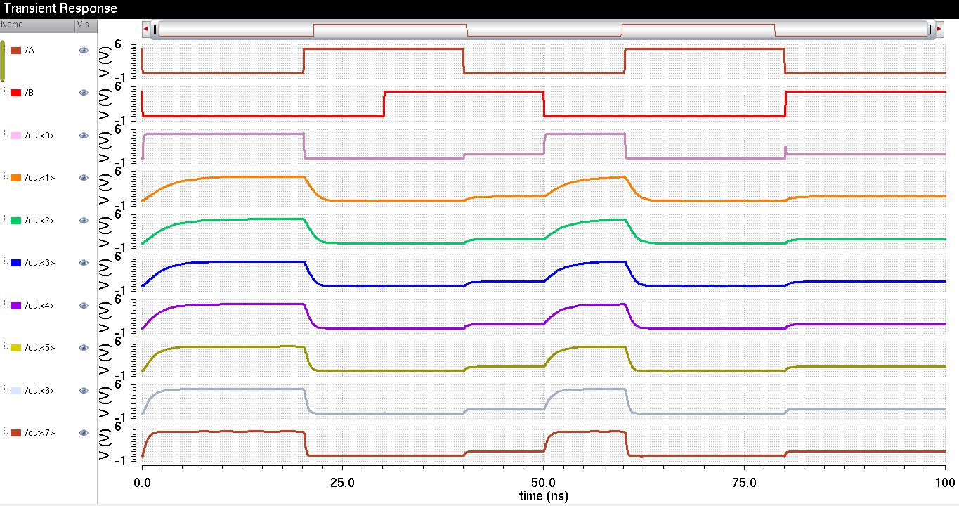
The image above shows the results of an 8-bit NOR gate using 6u/0.6u MOSFETs.


http://cmosedu.com/jbaker/courses/ee421L/f15/students/kieatiwo/Lab7/11.JPG

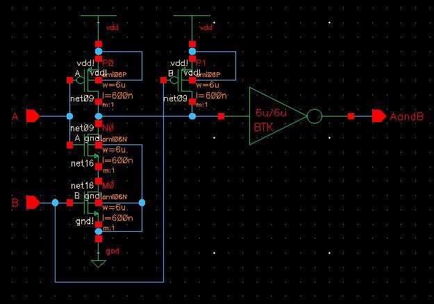
The image above shows the schematic of an AND gate using 6u/0.6u MOSFETs.


http://cmosedu.com/jbaker/courses/ee421L/f15/students/kieatiwo/Lab7/12.JPG

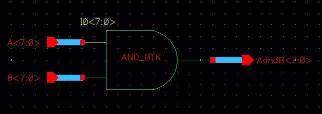
The image above shows the schematic of an 8-bit AND gate using 6u/0.6u MOSFETs.


http://cmosedu.com/jbaker/courses/ee421L/f15/students/kieatiwo/Lab7/13.JPG

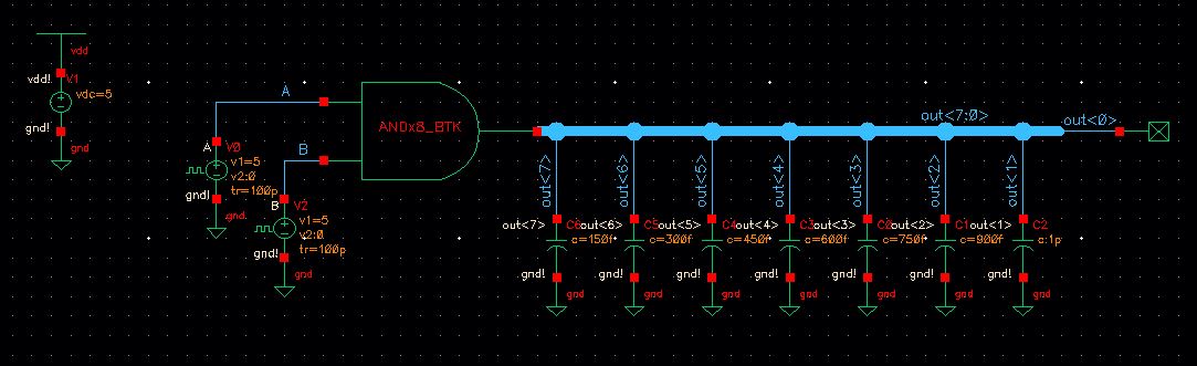
The image above shows the simulation schematic of an 8-bit AND gate using 6u/0.6u MOSFETs.


http://cmosedu.com/jbaker/courses/ee421L/f15/students/kieatiwo/Lab7/14.JPG

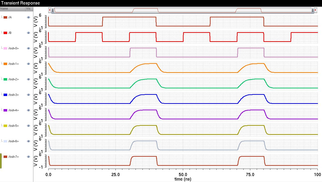
The image above shows the results of an 8-bit AND gate using 6u/0.6u MOSFETs.


http://cmosedu.com/jbaker/courses/ee421L/f15/students/kieatiwo/Lab7/15.JPG

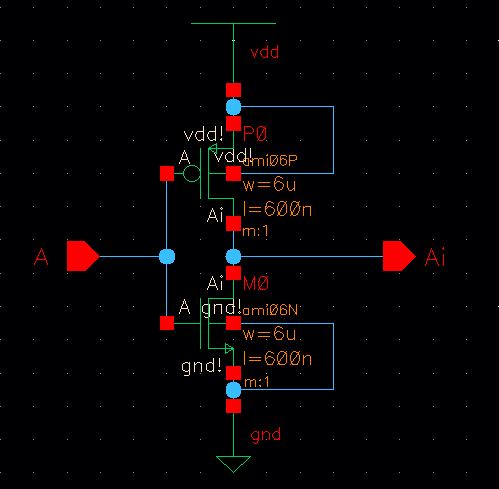
The image above shows the schematic of an inverter using 6u/0.6u MOSFETs.


http://cmosedu.com/jbaker/courses/ee421L/f15/students/kieatiwo/Lab7/16.JPG
The image above shows the schematic of an 8-bit inverter using 6u/0.6u MOSFETs.


http://cmosedu.com/jbaker/courses/ee421L/f15/students/kieatiwo/Lab7/17.JPG

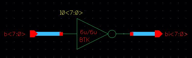
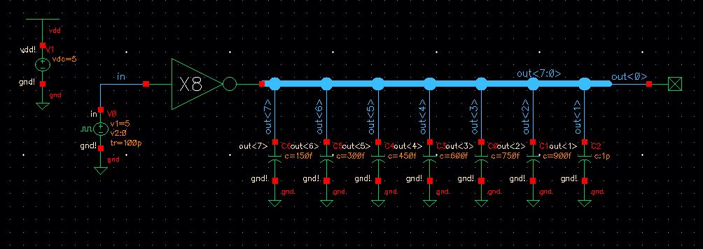
The image above shows the simulation schematic of an 8-bit inverter using 6u/0.6u MOSFETs.


http://cmosedu.com/jbaker/courses/ee421L/f15/students/kieatiwo/Lab7/18.JPG

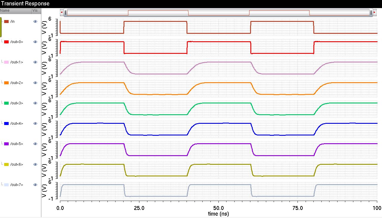
The image above shows the results of an 8-bit inverter using 6u/0.6u MOSFETs.


http://cmosedu.com/jbaker/courses/ee421L/f15/students/kieatiwo/Lab7/19.JPG

The image above shows the schematic of an OR gate using 6u/0.6u MOSFETs.
 

http://cmosedu.com/jbaker/courses/ee421L/f15/students/kieatiwo/Lab7/20.JPG

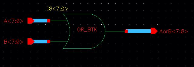
The image above shows the schematic of an 8-bit OR gate using 6u/0.6u MOSFETs.


http://cmosedu.com/jbaker/courses/ee421L/f15/students/kieatiwo/Lab7/21.JPG

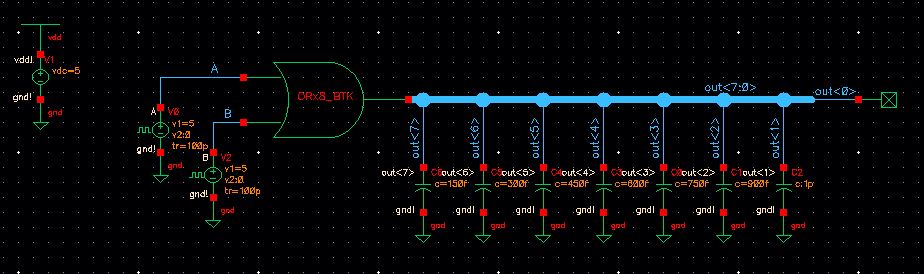
The image above shows the simulation schematic of an 8-bit OR gate using 6u/0.6u MOSFETs.


http://cmosedu.com/jbaker/courses/ee421L/f15/students/kieatiwo/Lab7/22.JPG

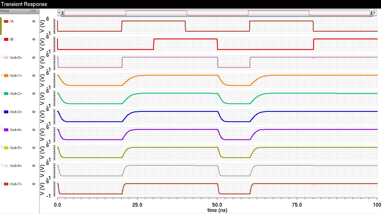
The image above shows the results of an 8-bit OR gate using 6u/0.6u MOSFETs.


http://cmosedu.com/jbaker/courses/ee421L/f15/students/kieatiwo/Lab7/23.JPG

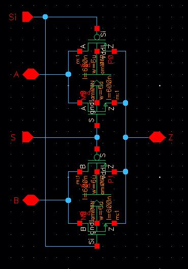
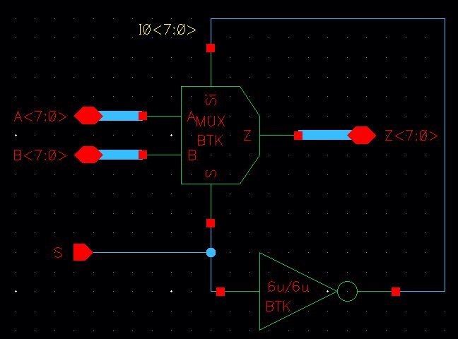
The image above shows the schematic of a 2-to-1 MUX gate using 6u/0.6u MOSFETs. This can also be used as a DEMUX by reversing the the input and outputs to be 1-to-2 DEMUX.


http://cmosedu.com/jbaker/courses/ee421L/f15/students/kieatiwo/Lab7/25.JPG
The image above shows the simulation schematic of a 2-to-1 MUX gate using 6u/0.6u MOSFETs.
 

http://cmosedu.com/jbaker/courses/ee421L/f15/students/kieatiwo/Lab7/26.JPG

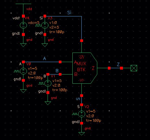
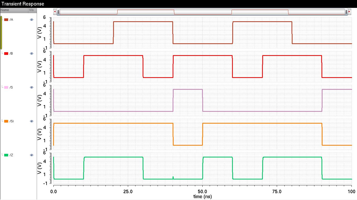
The image above shows the results of a 2-to-1 MUX gate using 6u/0.6u MOSFETs.


http://cmosedu.com/jbaker/courses/ee421L/f15/students/kieatiwo/Lab7/24.JPG

The image above shows the schematic of an 8-bit 2-to-1 MUX gate using 6u/0.6u MOSFETs.
 

http://cmosedu.com/jbaker/courses/ee421L/f15/students/kieatiwo/Lab7/27.JPG

The images above shows how Lab 7 work is to be zipped and emailed to myself for backup.


To download the cells from this lab, click here.


Return to EE421L Labs