Lab 5 - EE 421L
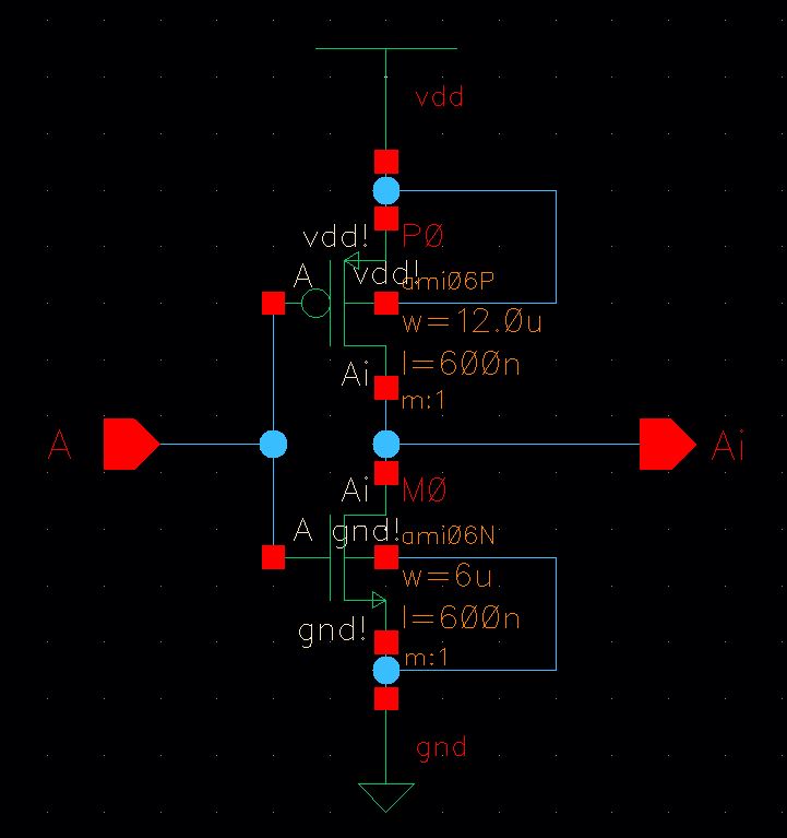
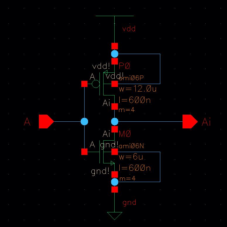
The image above shows the schematic of the 12u/6u inverter.
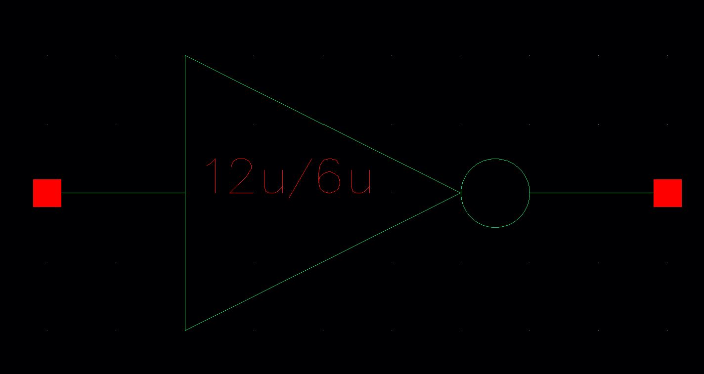
The image above shows the symbol of the 12u/6u inverter.
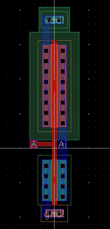
The image above shows the layout of the 12u/6u inverter.
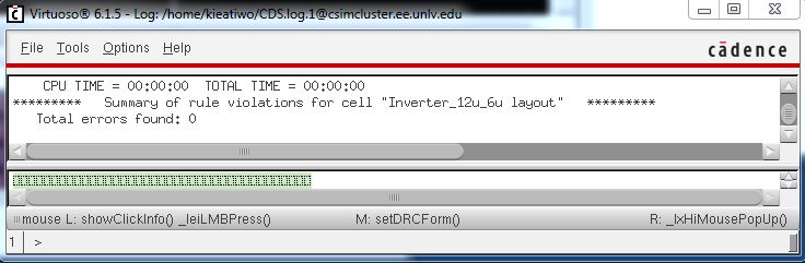
The image above shows the successful DRC of the 12u/6u inverter.
The image above shows the schematic of the 48u/24u inverter.
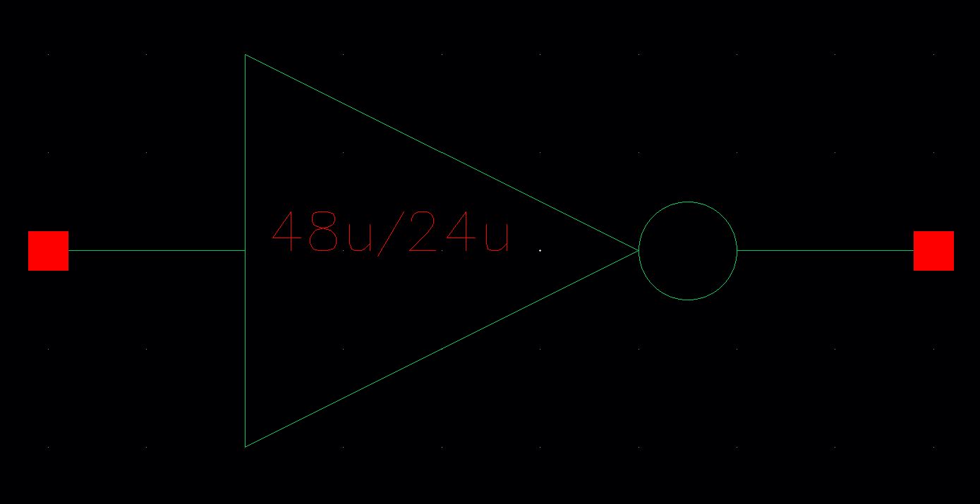
The image above shows the symbol of the 48u/24u inverter.
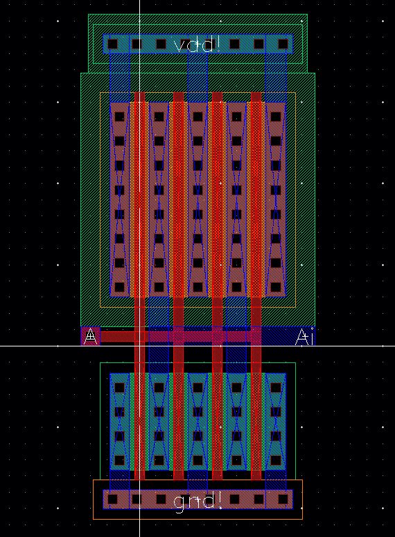
The image above shows the layout of the 48u/24u inverter.
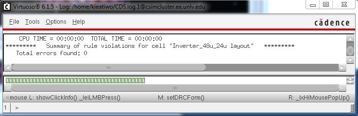
The image above shows the successful DRC of the 48u/24u inverter.
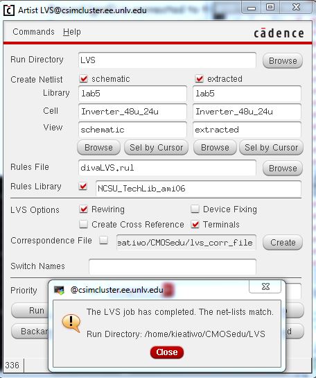
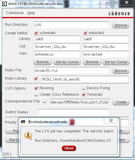
The image above shows the successful LVS of the 48u/24u inverter.
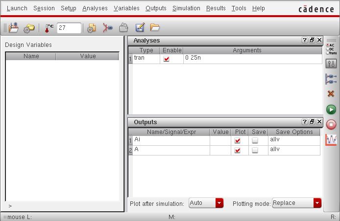
The image above shows the parameters for all the simulation results below.
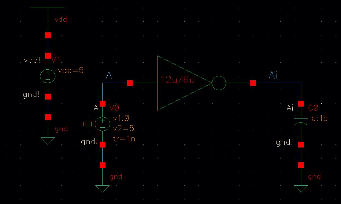
The image above shows the schematic of a 12u/6u inverter driving a 1pF capacitive load.
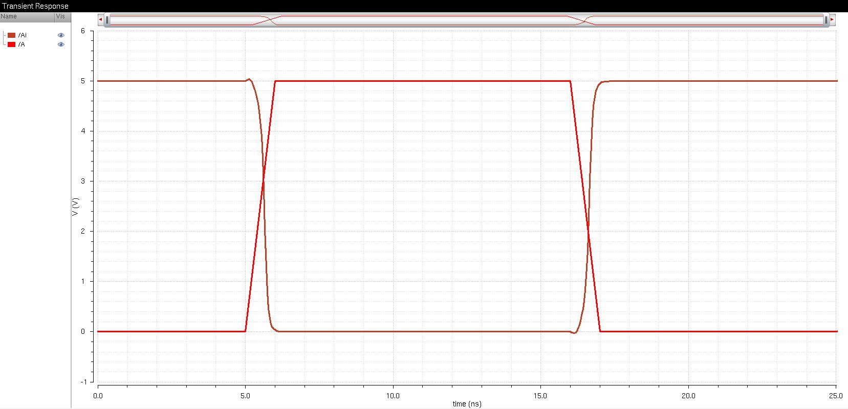
The image above shows the SPICE results of a 1pF capacitive load.
The image above shows the UltraSim results of a 1pF capacitive load.
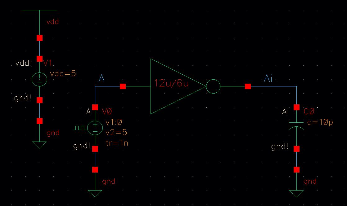
The image above shows the schematic of a 12u/6u inverter driving a 10pF capacitive load.
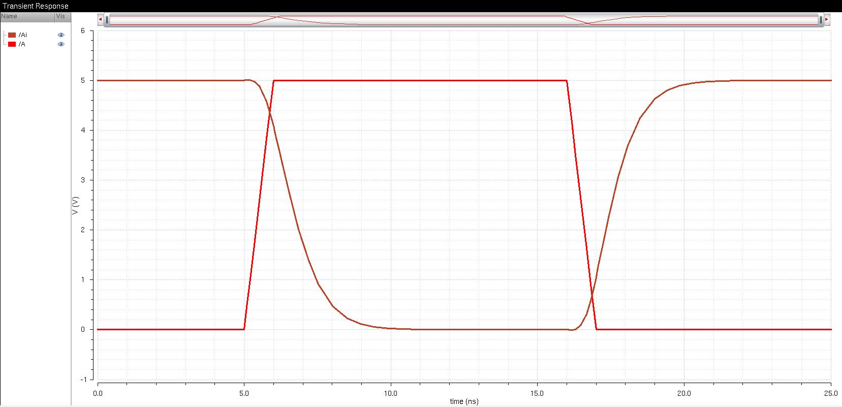
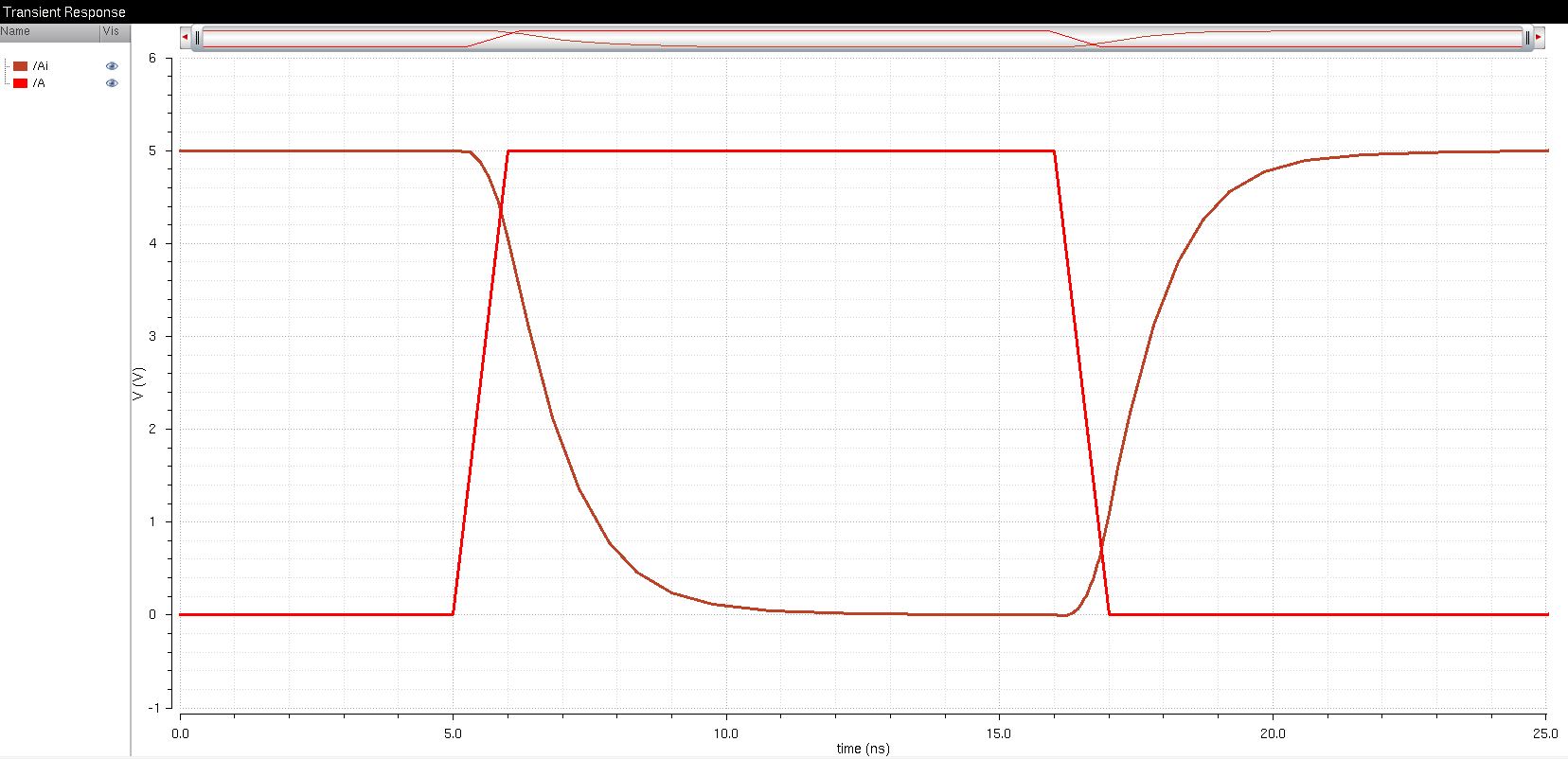
The image above shows the SPICE results of a 10pF capacitive load.
The image above shows the UltraSim results of a 10pF capacitive load.
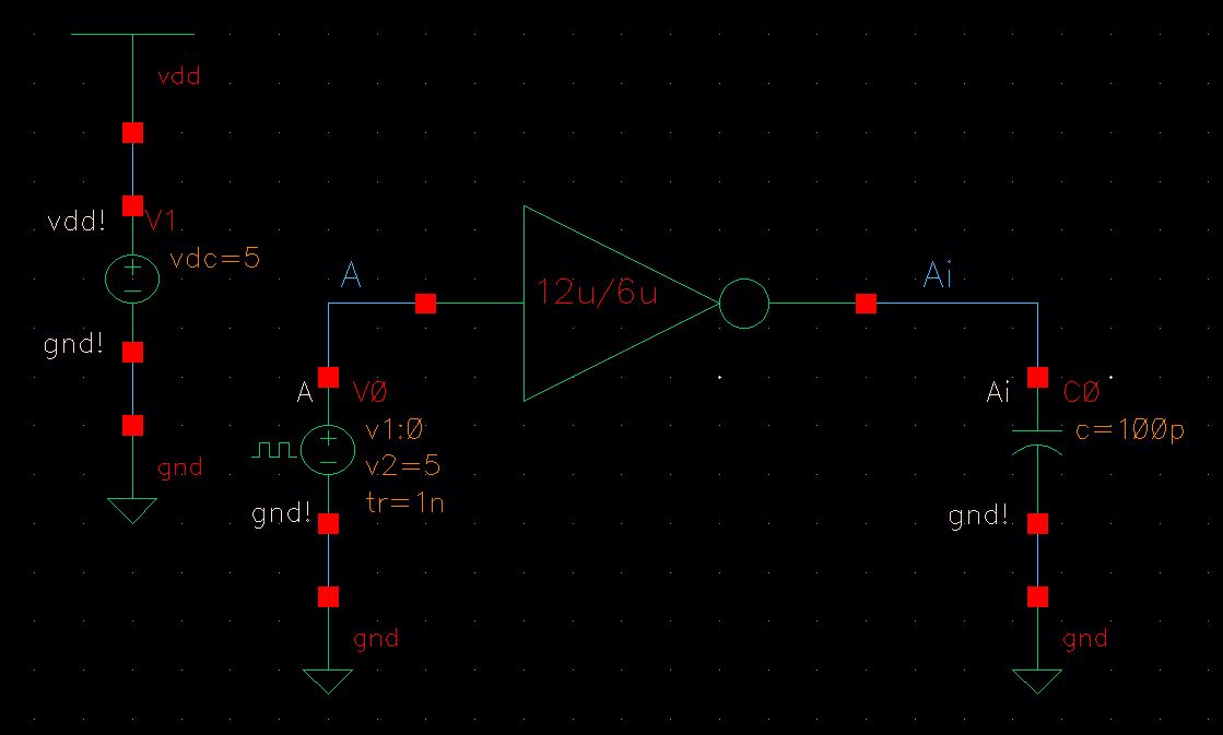
The image above shows the schematic of a 12u/6u inverter driving a 100pF capacitive load.
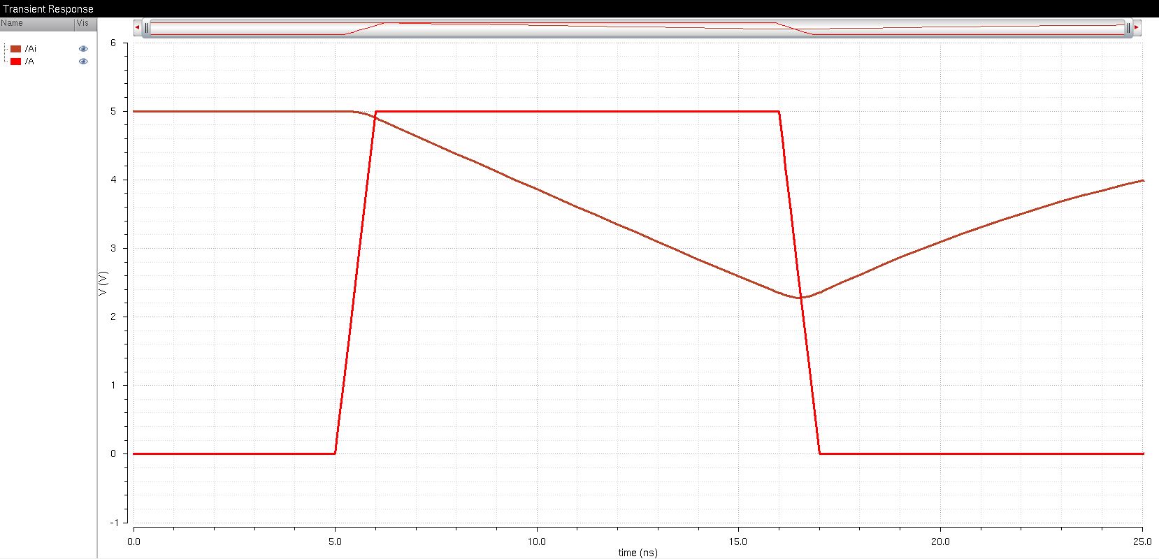
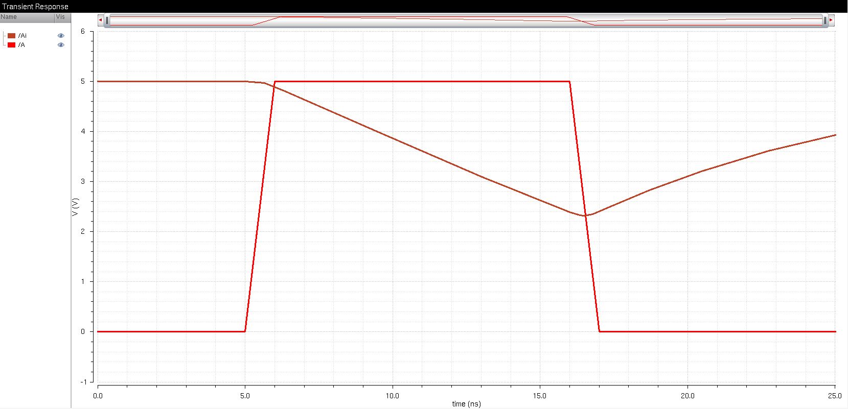
The image above shows the SPICE results of a 100pF capacitive load.
The image above shows the UltraSim results of a 100pF capacitive load.
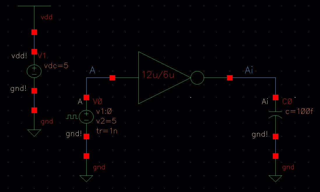
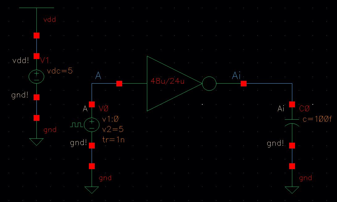
The image above shows the schematic of a 12u/6u inverter driving a 100fF capacitive load.
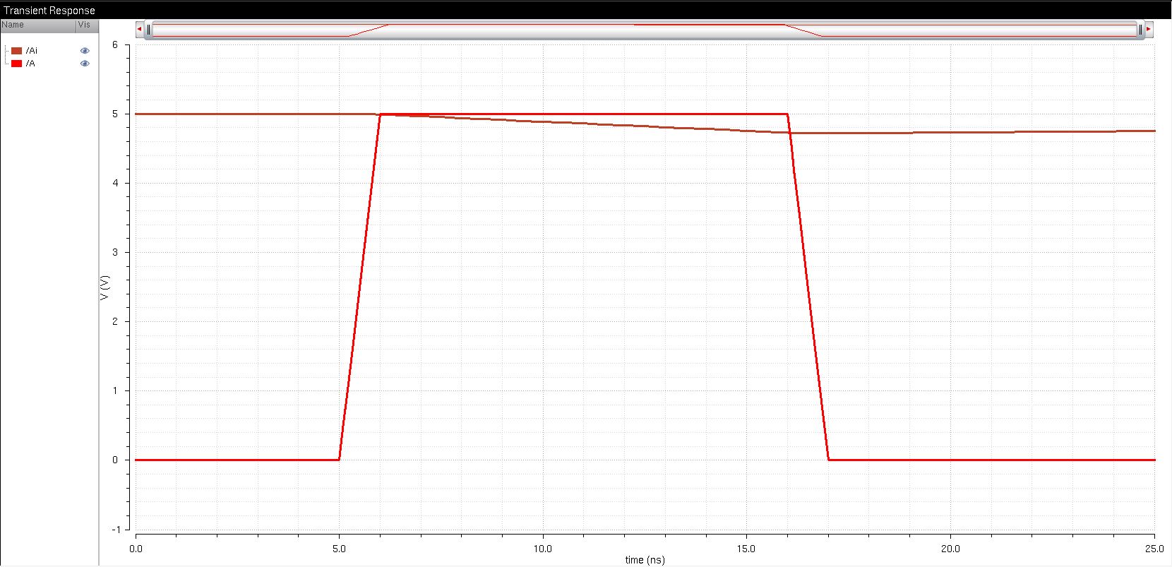
The image above shows the SPICE results of a 100fF capacitive load.
The image above shows the UltraSim results of a 100fF capacitive load.
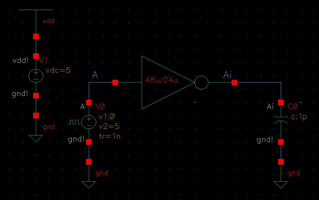
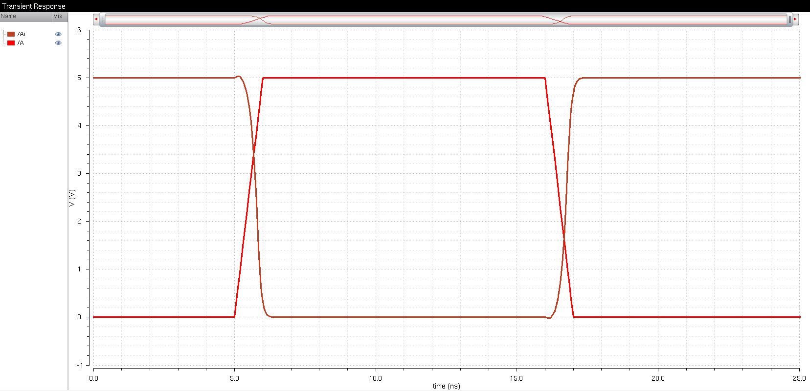
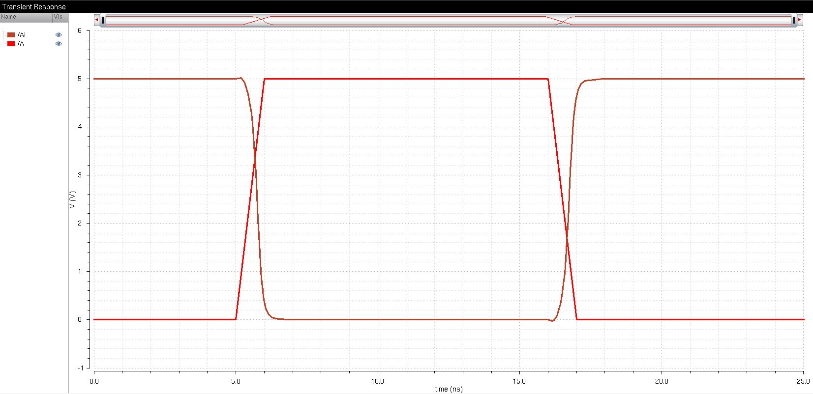
The image above shows the schematic of a 48u/24u inverter driving a 1pF capacitive load.
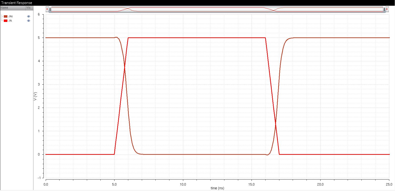
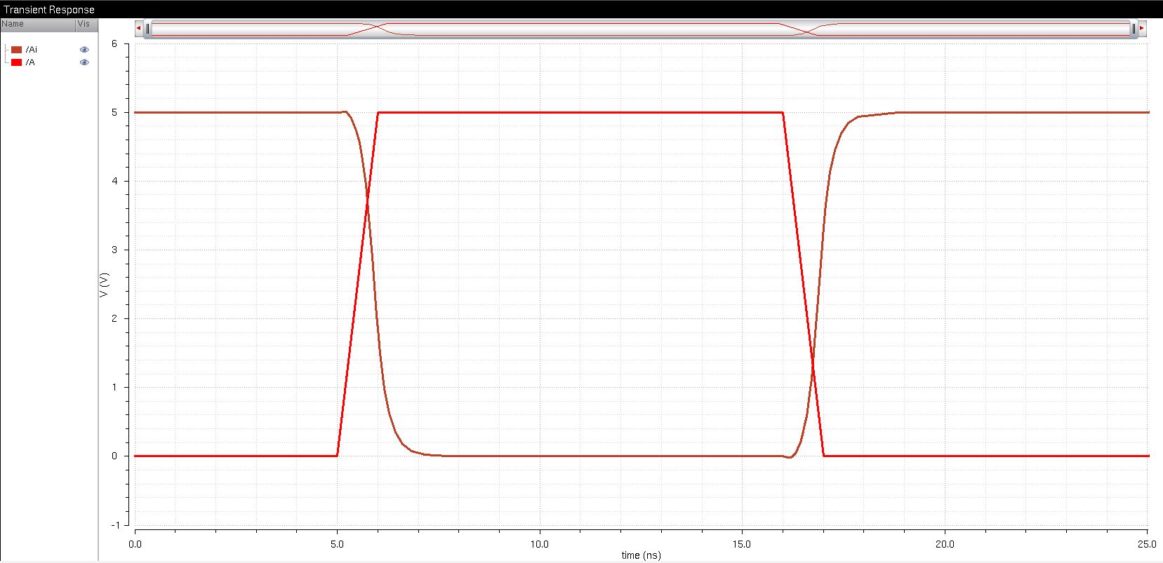
The image above shows the UltraSim results of a 1pF capacitive load.
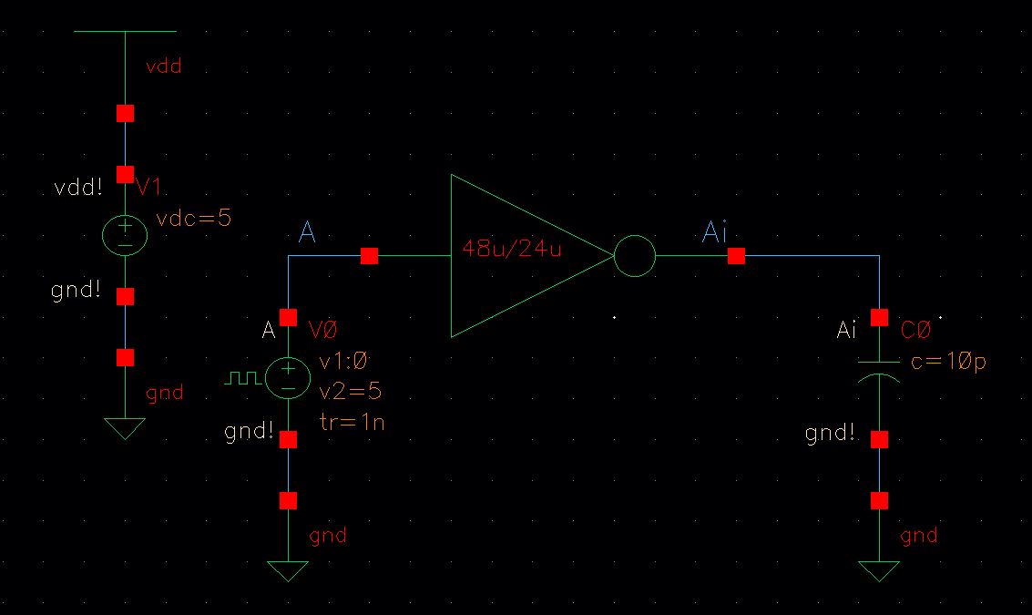
The image above shows the schematic of a 48u/24u inverter driving a 10pF capacitive load.
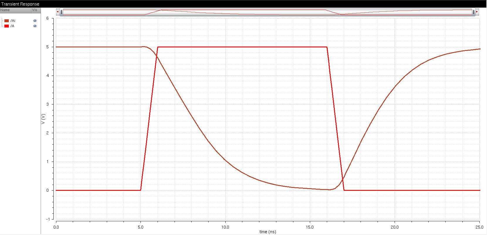
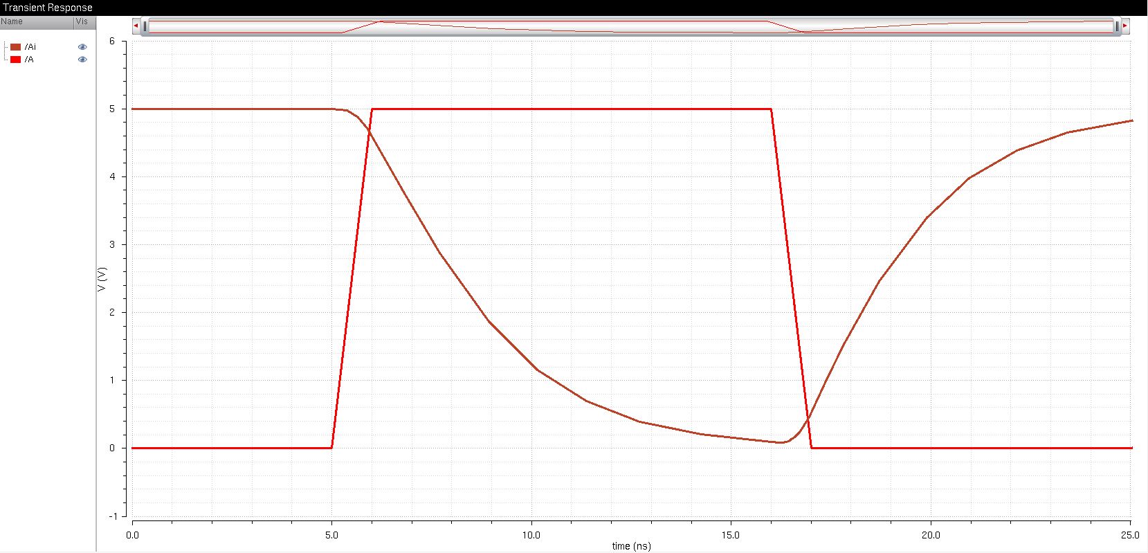
The image above shows the UltraSim results of a 10pF capacitive load.
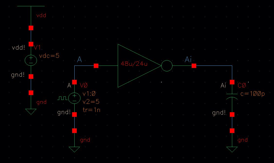
The image above shows the schematic of a 48u/24u inverter driving a 100pF capacitive load.

The image above shows the SPICE results of a 100pF capacitive load.
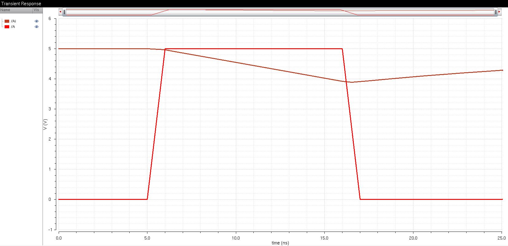
The image above shows the UltraSim results of a 100pF capacitive load.
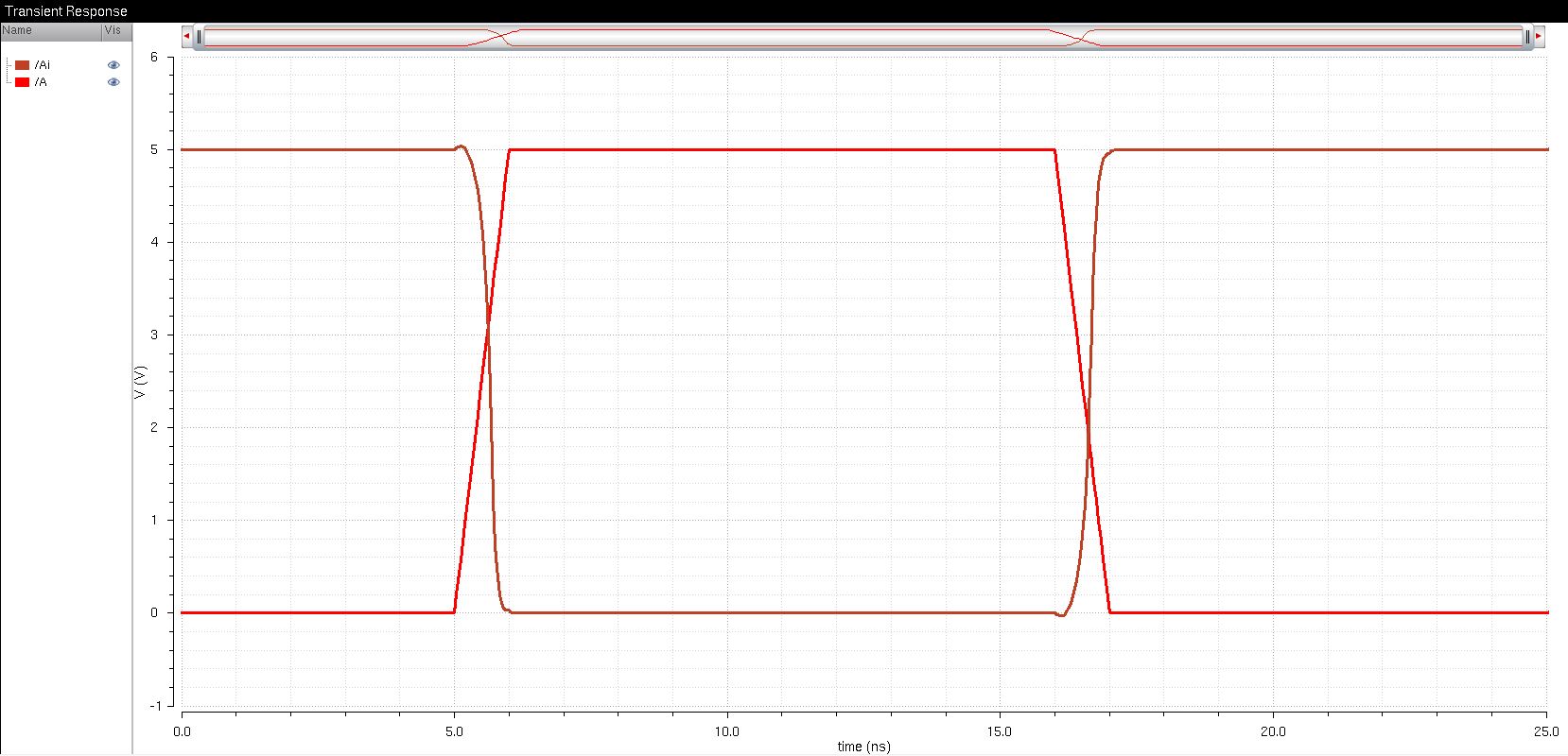
The image above shows the SPICE results of a 100fF capacitive load.
The image above shows the UltraSim results of a 100fF capacitive load.
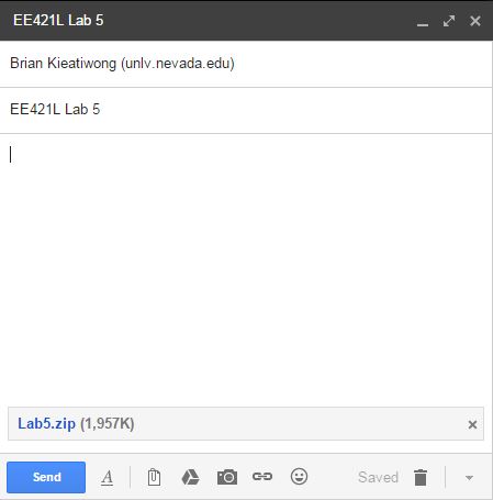
The images above shows how Lab 4 work is to be zipped and emailed to myself for backup.
To download the cells from this lab, click here.