Lab 3 - EE 421L
Authored
by Brian Kieatiwong
kieatiwo@unlv.nevada.edu
09/21/15
This
lab consists of layout design of the 10-bit DAC fromt the previous lab.
It will also show that the layout adheres to the DRC and LVS. This lab
will also show the backing up of all lab
work.
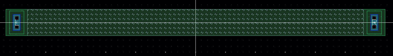
The
image above shows the layout of a 10k resistor using the n-well. By use
of the process information from MOSIS, the proper dimensions were
obtained.
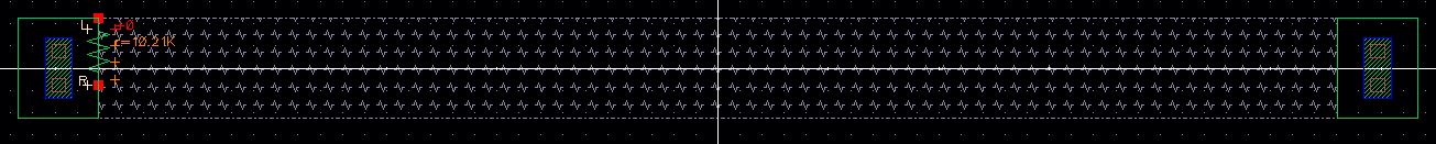
The
image above shows the extracted layout of the 10k resistor using the
n-well. This shows that the dimensions chosen were appropriate in
creating approximately 10k ohms.
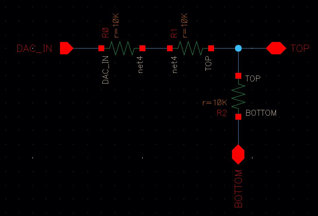
The image above shows the schematic of a single DAC that will be used to create a 10-bit DAC.
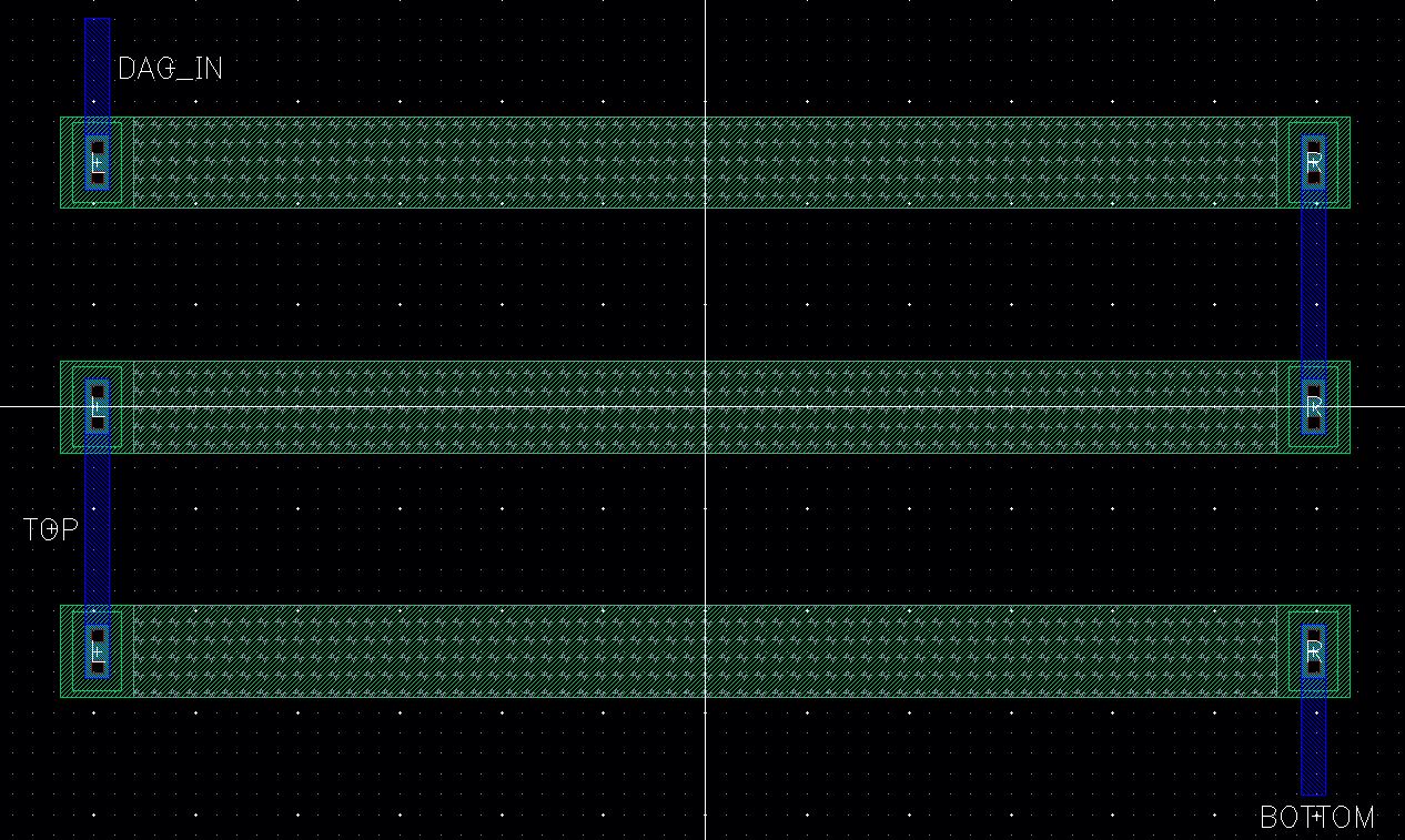
The image above shows the layout of the single DAC by using the layout of the 10k resistor.
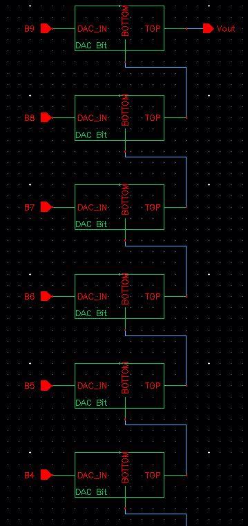
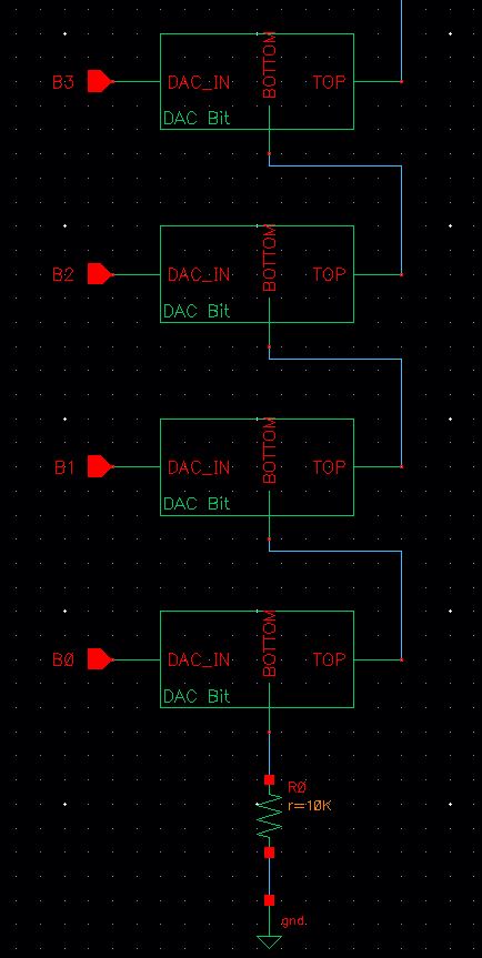
The image above shows the schematic of the 10-bit DAC that will be used to create the layout.
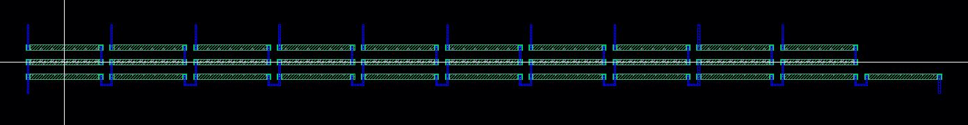
The image above shows the full layout of the 10-bit DAC.
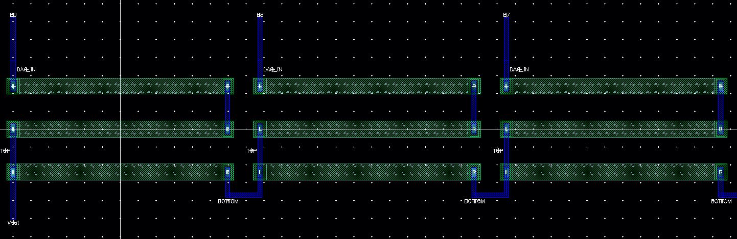
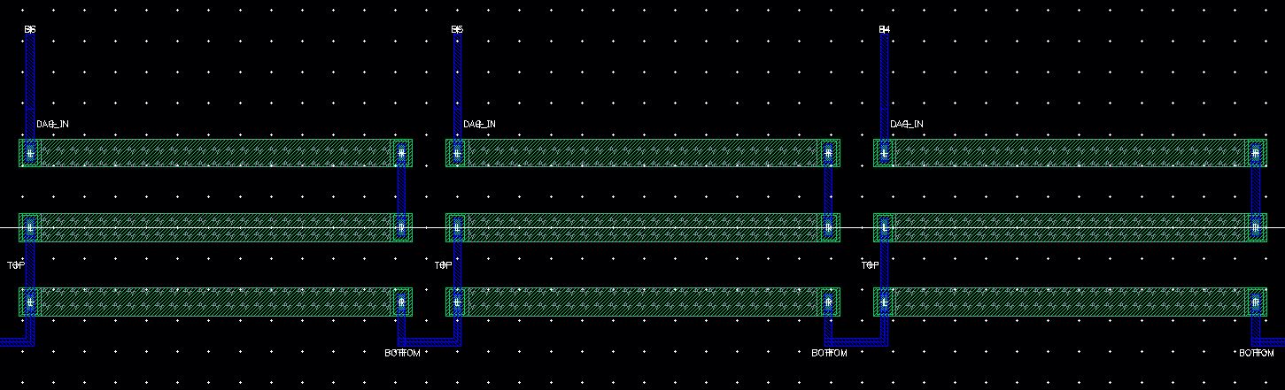
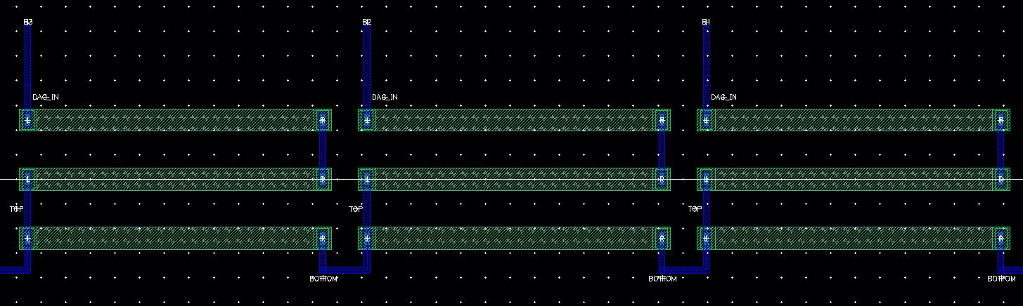
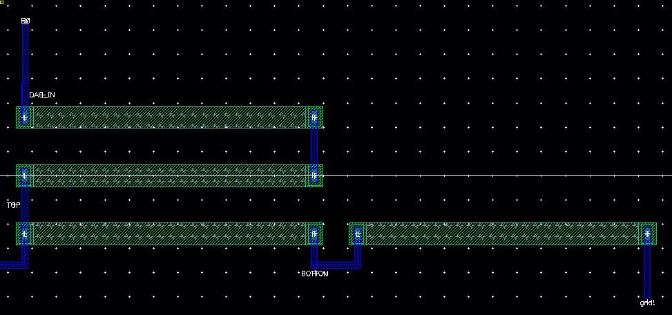
The
images shown above are the enlarged views of the 10-bit DAC layout.
Each image shows the respective inputs for the 10-bit DAC.
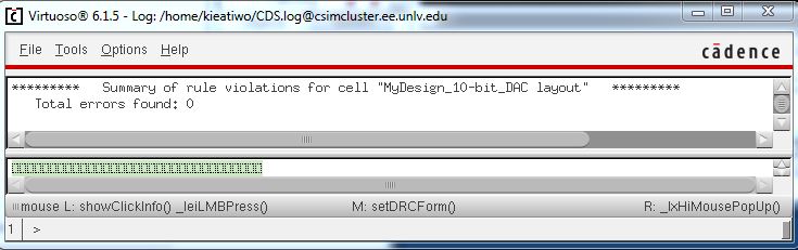
The image above shows that the 10-bit DAC has properly passed the DRC.
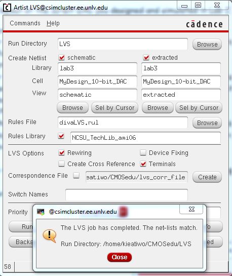
The image above shows that the 10-bit DAC has also properly passed the LVS.
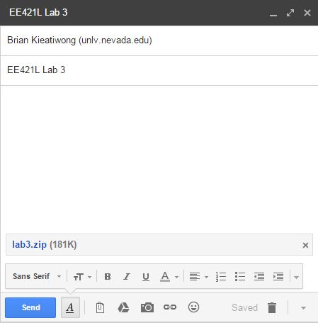
The images above shows how Lab 3 work is to be zipped and emailed to myself for backup.
Return to EE421L Labs