Lab X - ECE 421L
Lab 2: 10-bit ADC
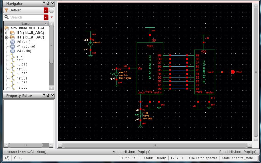
The prelab led through the steps to create a new library and use it to run a simulation of an ideal 10-bit Anolog-to-Digital Converter connected to an ideal 10-bit Digital-to-Analog converter.
Below is the schematic:
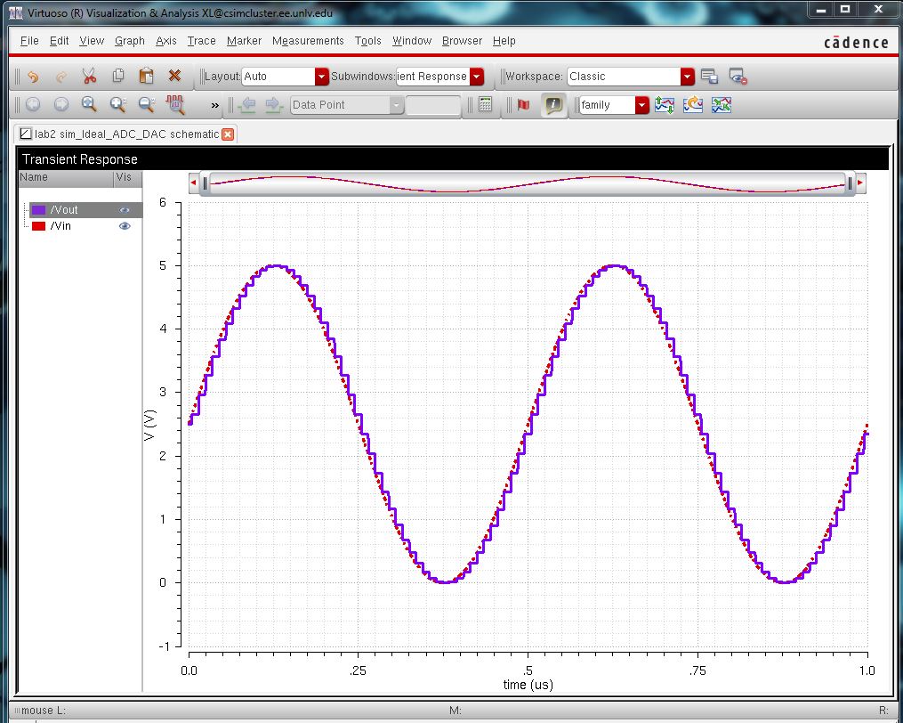
Below is the simulated output:
Now the task is to create a layout that mimics the ideal DAC using 10k Ohm n-well resistors.
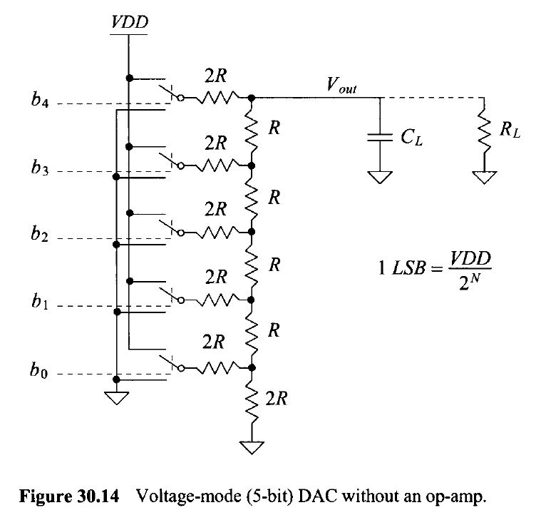
The topology that will be used for this lab is and R-2R topology:
The shematic:
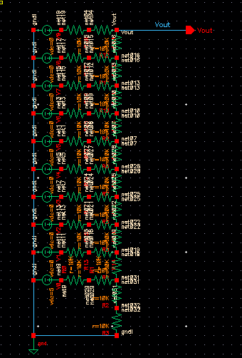
2x 10k Ohm resistors were used in series for each value of 2R.
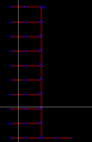
Below is the layout of n-well resistors:
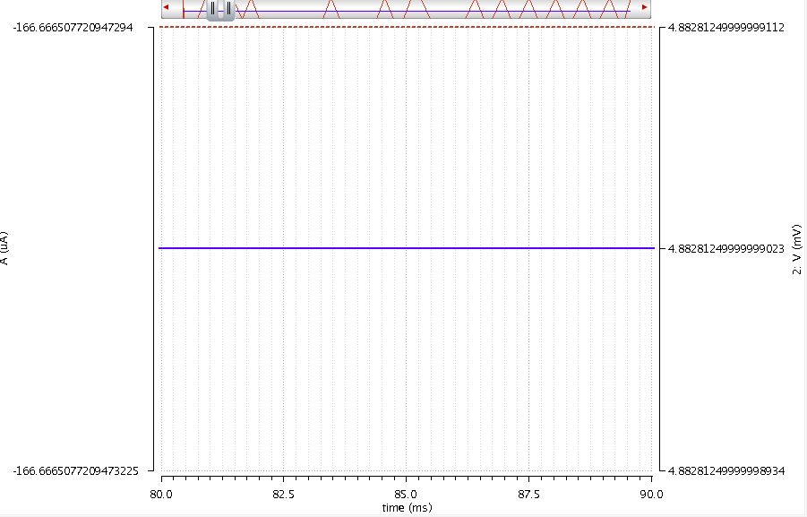
Below is the output of just the least significant bit (LSB):
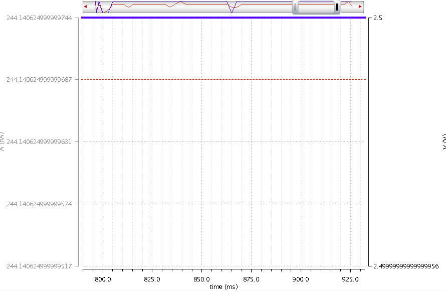
and the output of the most significant bit (MSB):
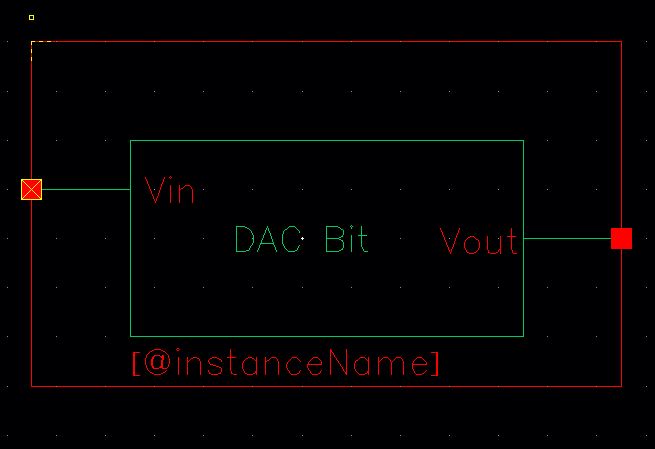
Below is the associtated symbol for this circuit: