Lab 1 - EE 421L Fall 2015

Mario De La Torre

delatm2@unlv.nevada.edu

8/22/2015 


Lab description:

This lab shows how to edit/create  webpages at CMOSedu.com and how to set up Cadence for use with ON's C5 process, followed by the design and simulation of a voltage divider circuit.

 Part 1:

Steps to step up Cadence to do DRC, Extract and LVS layouts.

A) In the directory $HOME/ncsu-cdk-1.6.0.beta/lib/NCSU_TechLib_ami06 delete the files divaDRC.rul, divaEXT.rul, and divaLVS.rul. 


http://cmosedu.com/jbaker/courses/ee421L/f15/students/delatm2/Lab1/step_a.JPG


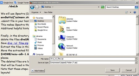
B) Save diva_rul_files.zip to your desktop.


http://cmosedu.com/jbaker/courses/ee421L/f15/students/delatm2/Lab1/step_b.JPG


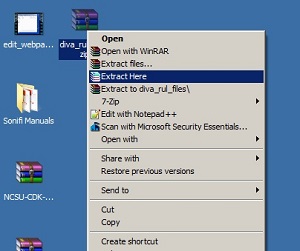
C) Extract the files in this zip to your desktop.


http://cmosedu.com/jbaker/courses/ee421L/f15/students/delatm2/Lab1/step_c.JPG


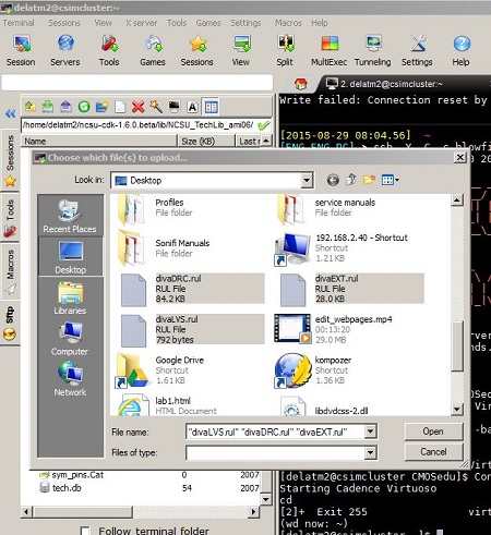
D) Upload the extracted files (divaDRC.rul, divaEXT.rul, and divaLVS.rul) into $HOME/ncsu-cdk-1.6.0.beta/lib/NCSU_TechLib_ami06 in the deleted files’ places.


http://cmosedu.com/jbaker/courses/ee421L/f15/students/delatm2/Lab1/step_d_move.JPG


Done now everything is setup to do a simulation.


The following step will show how to design and simulate a voltage divider circuit:


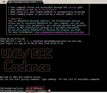
1. Open a terminal window and change directories to CMOSedu by typing cd CMOSedu to change the directory then type virtuoso & to start Cadence's Virtuoso.


http://cmosedu.com/jbaker/courses/ee421L/f15/students/delatm2/Lab1/step1.JPG


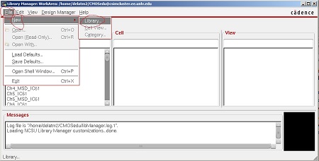
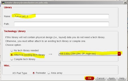
2. In the Library Manager window, click File -> New -> Library and name it "Tutorial_1".  Click  on Attach to existing tech library and select  "AMI 0.60u C5(3M, 2P, high-res)" from the drop menu, then click OK.


http://cmosedu.com/jbaker/courses/ee421L/f15/students/delatm2/Lab1/step2.JPG


http://cmosedu.com/jbaker/courses/ee421L/f15/students/delatm2/Lab1/step2a.JPG


3. In the Library Manager window select the Tutorial_1 libary.  Click file, new, and cell view. This will bring up the following window, name the cell R_div then click OK.  Now we are ready to build the schematic.


http://cmosedu.com/jbaker/courses/ee421L/f15/students/delatm2/Lab1/step3.JPG

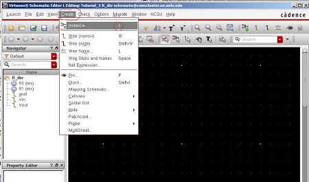
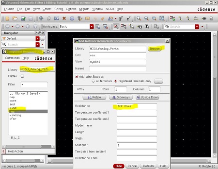
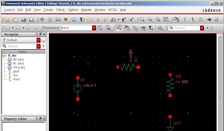
4. On the new window with the black background press "i" to add the resistors.   To do this you click on "Browse" then Library you select NCSU_Analog_Parts, then R_L_C, then select "res" and finally enter the value.


  http://cmosedu.com/jbaker/courses/ee421L/f15/students/delatm2/Lab1/step4a.JPG


 Select the "res" and enter 10k for the value:

http://cmosedu.com/jbaker/courses/ee421L/f15/students/delatm2/Lab1/step4.JPG


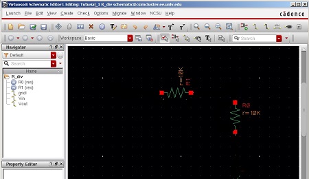
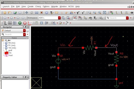
Schematic with two resistors.


http://cmosedu.com/jbaker/courses/ee421L/f15/students/delatm2/Lab1/step4b.JPG


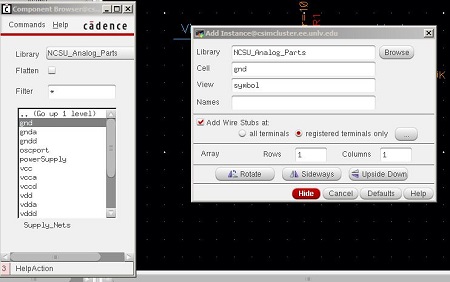
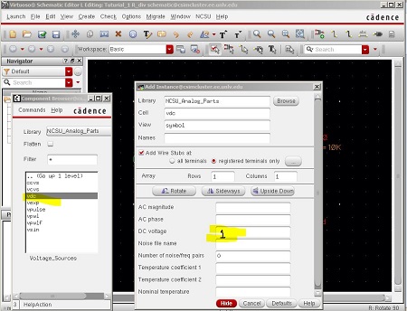
5. Similarly, to add the ground and power supply:


http://cmosedu.com/jbaker/courses/ee421L/f15/students/delatm2/Lab1/step4_ground.JPG


http://cmosedu.com/jbaker/courses/ee421L/f15/students/delatm2/Lab1/step4_vdc.JPG


http://cmosedu.com/jbaker/courses/ee421L/f15/students/delatm2/Lab1/step4c.jpg

6. Add wires by pressing "w" and label the input and output nodes by pressing "L" lower case and then click "check and save" button.


 http://cmosedu.com/jbaker/courses/ee421L/f15/students/delatm2/Lab1/step7_complete_circuit.JPG


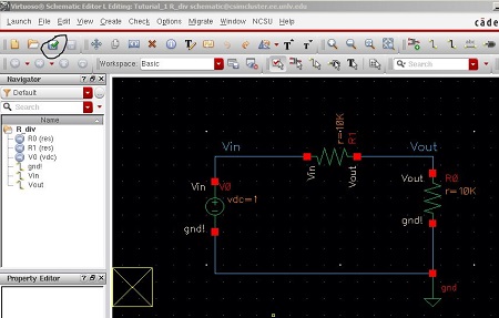
Now we are ready to simulate the circuit.


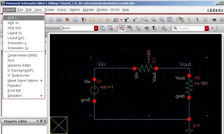
7. Click Launch, and ADE L.


 http://cmosedu.com/jbaker/courses/ee421L/f15/students/delatm2/Lab1/step10_launchADE.jpg


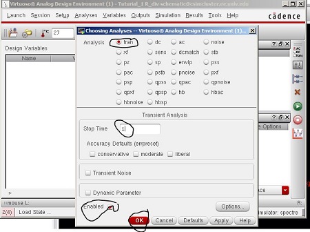
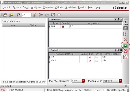
8.  On the Virtuoso Analog Design Environment (ADE) window  go to Analyses -> Choose and select a transient analysis (tran), a stop time of 1 second, and Enabled as seen below.


http://cmosedu.com/jbaker/courses/ee421L/f15/students/delatm2/Lab1/step11_choosing.JPG


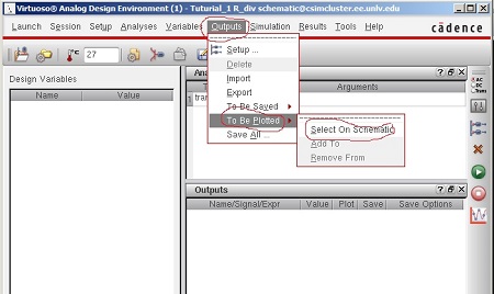
9. Next select the signals we want to plot. Click on Outputs -> To Be Plotted -> Select On Schematic.


http://cmosedu.com/jbaker/courses/ee421L/f15/students/delatm2/Lab1/step12_output.jpg


 10. Select the points on the schematic. 


http://cmosedu.com/jbaker/courses/ee421L/f15/students/delatm2/Lab1/step12_output_a.JPG


11.  Click Run.


http://cmosedu.com/jbaker/courses/ee421L/f15/students/delatm2/Lab1/step13_run.JPG


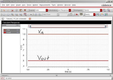
12. Verify output and done.


http://cmosedu.com/jbaker/courses/ee421L/f15/students/delatm2/Lab1/step14_sim_out.JPG


Sample of a table


 Part 2:

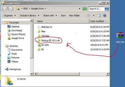
Procedure on how to backup my work.

1. A zip folder will be created labX.


http://cmosedu.com/jbaker/courses/ee421L/f15/students/delatm2/Lab1/zipfolder.JPG

2. Then the zipped folder will be store on my google drive.


http://cmosedu.com/jbaker/courses/ee421L/f15/students/delatm2/Lab1/googledrive.JPG

Return to delatm2 lab directory


Return to EE 421L Labs