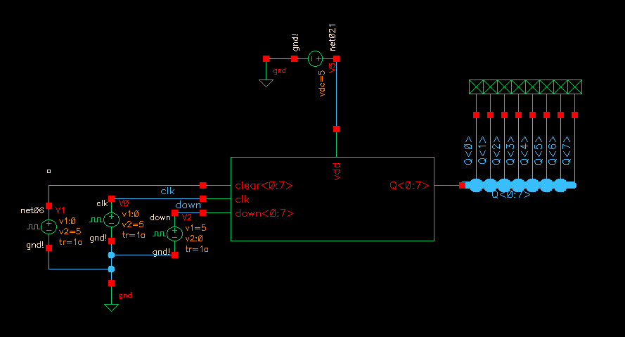
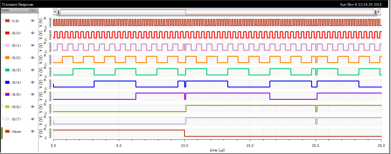
Above is a schematic that was used to simulate the functionality of the up/down counter. At 10us the counter clears and switches from counting up to counting down.
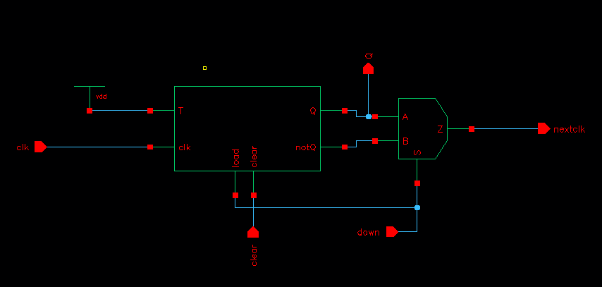
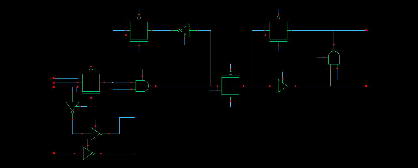
To the left is a schematic of a one bit counter. To the right is the implementation of a D-Flip-Flop.
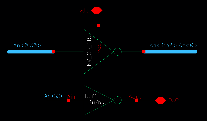
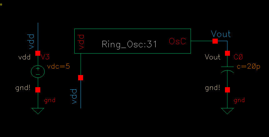
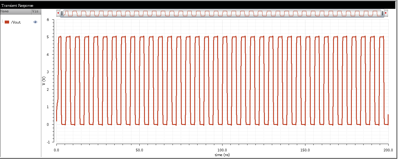
Above are the schematics that correspond to the ring oscillator along with a simulation
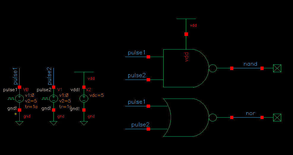
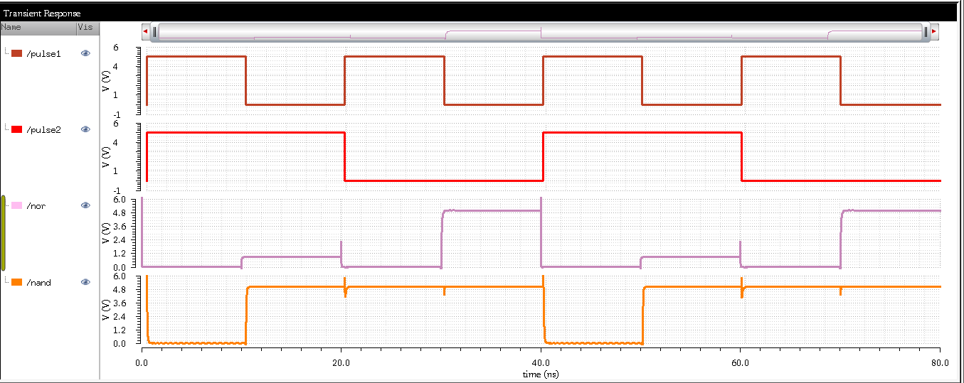
Here are example runs of a NAND and NOR gate created with 6u/.6u MOSFETS.
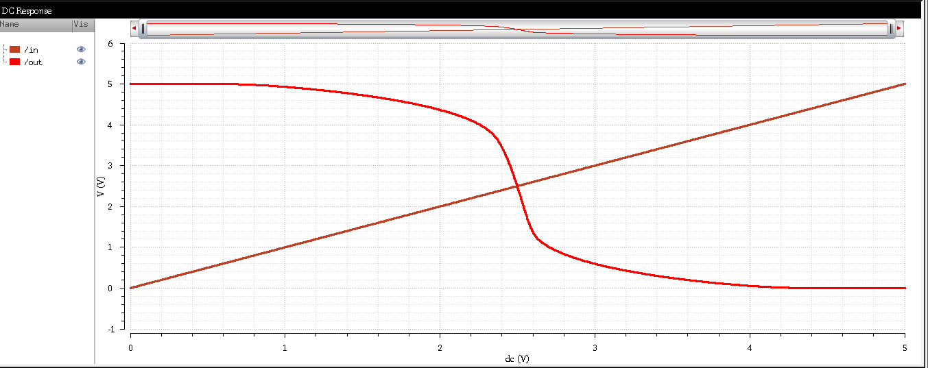
Above is a schematic and a simulation of an ideal inverter. Notice how the switching point value is measure directly at 2.5 V.
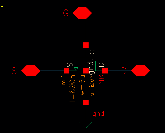
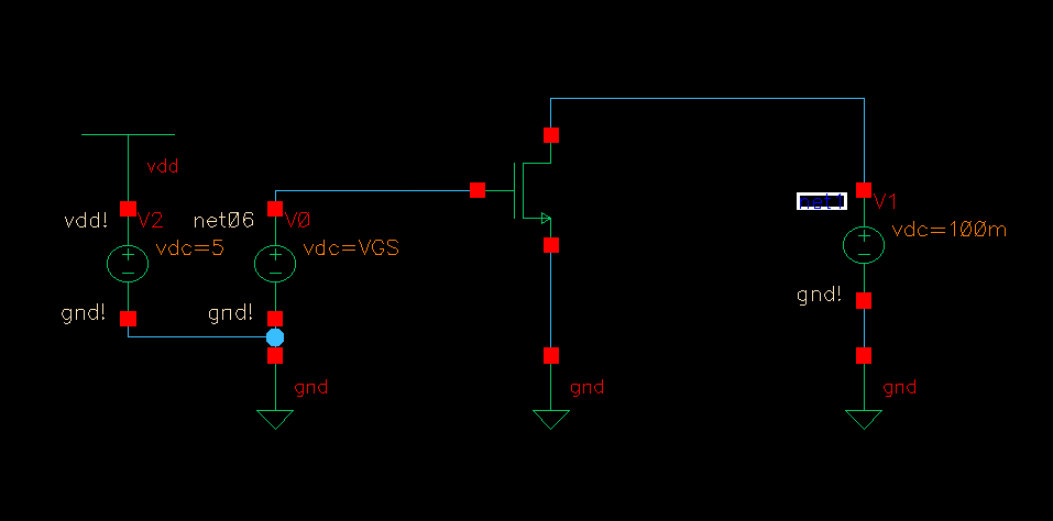
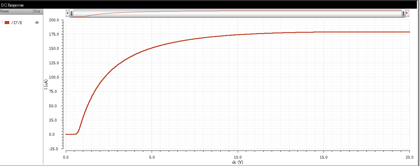
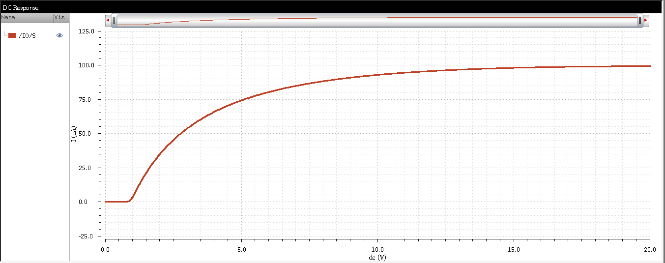
Above are the schematics and the correspnding simulation of the NMOS transistor with a 6u/.6u width and length.
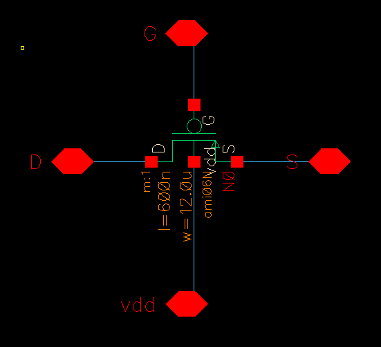
Above are the schematics and the correspnding simulation of the PMOS transistor with a 6u/.6u width and length.
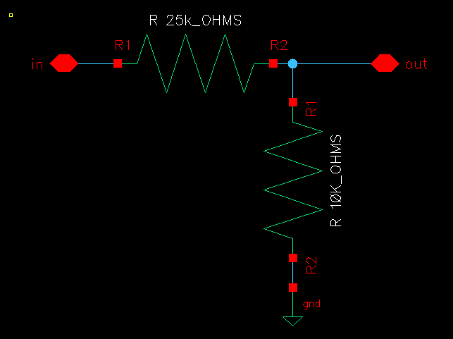
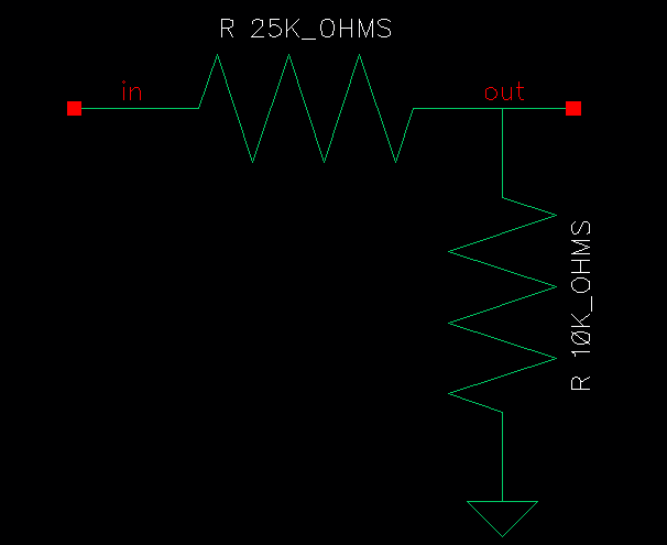
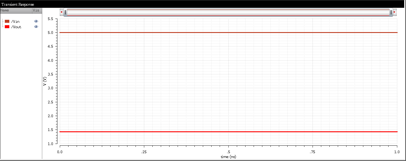
Above is the voltage divider schematic, symbol, and simulation. Notice how the output voltage is a ratio of the input voltage that is determined by the values of the two resistors.
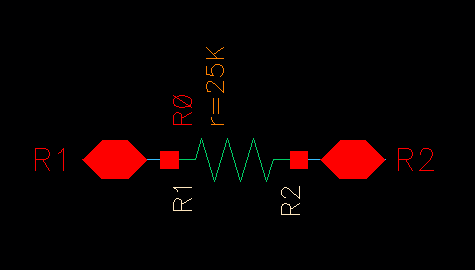
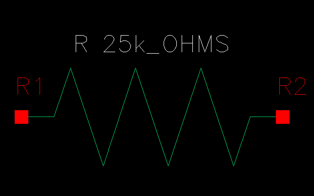
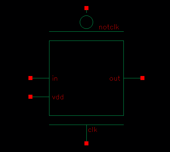
Here is the symbol and schematic of the 25k resistor
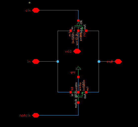
Above is the schematic of the transmission gate and also the corresponding symbols. The transmission gate allows us to pass distinguishable logic highs and logic lows.
Click the link below to download the project files
project files
Originally my design for the 8 bit counter was constructed with D-flip-flops. Unfortunately
we encountered a timing issue and decided to use a design that incorporated a synchronized clock.
The J-K-flip-flop implementation of the counter allowed us to correctly remember the previous
state of register, which made it possible to assert or deassert the direction of the counter.
Below are the results.
Above is the 8-bit implementation of the counter. The image on the left is the actual schematic.
The image on the right is the schematic's corresponding symbol.
The above images show the layout of the 8-bit counter and also that the layout succesfully
LVS'd.
To the left is a schematic of a one bit counter. We modified the D-Flip-Flop in order to
perform as a J-K-Flip-Flop.
Above is the schematic and the layout that correspond to the ring oscillator.
The image to the left shows that the ring oscillator passed the LVS check. The image to the right
shows the simulation of the ring oscillator.
Here are example runs of a NAND and NOR gate created with 6u/.6u MOSFETS.
The the left is the layout for the NAND gate and to the right is the layout for the NOR gate.
The the left is the LVS check for the NAND gate and to the right is the lvs check for the NOR gate.
Above is a schematic and the layout of an inverte with a 12u/6u PMOS to NMOS ratio.
Above is the shows the inverter passed the LVS checks. To the right of the first image shoes
the simulation results. Notice how the switching point voltage is close to ideal (2.5 V).
The image on the right shows the schematic of both the NMOS and PMOS transistors. To the
right is an image of the corresponding layout.
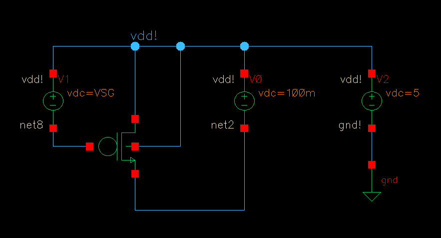
Above are two images that show the current-voltage characteristics of both the PMOS and NMOS devices.
The image to the left is for the PMOS and the image to right is for the NMOS.
Above is an image of the voltage divider's schematic. To its right is the layout.
The image to the left shows the voltage divider passes the LVS checks. The image to the right
shows the simulation results of the voltage divider.
Here is the symbol and schematic of the 25k resistor.
The image to the right shows the 25k ohm resistor passes the LVS checks. The image to the left
shows the simulation results of the 25k ohm resistor.
Above is the schematic of the transmission gate and also the corresponding symbols. The transmission gate allows us to pass distinguishable logic highs and logic lows.
The image to the left is the layout for the transmission gate. The image to the right shows that
the transmission gate passes the LVS checks.
Click the link below to download the project files
project files