Lab 1 - ECE 421L
Prepared by:
Jason Sikorski
sikorsk4@unlv.nevada.edu
Sept 8, 2014
Lab
description:
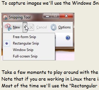
The first part of the Lab went through editing webpages using KompoZer and adding screenshots seen below:
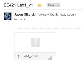
The second part of the Lab was
to go through the procedure for backing up your work. This was done
by zipping the folder I was working in and mailing it to myself, as
seen below:
The third part of the Lab was to go over the first Tutorial in Cadence and create a resistive voltage divider.
This was done using an Xterm from my Mac
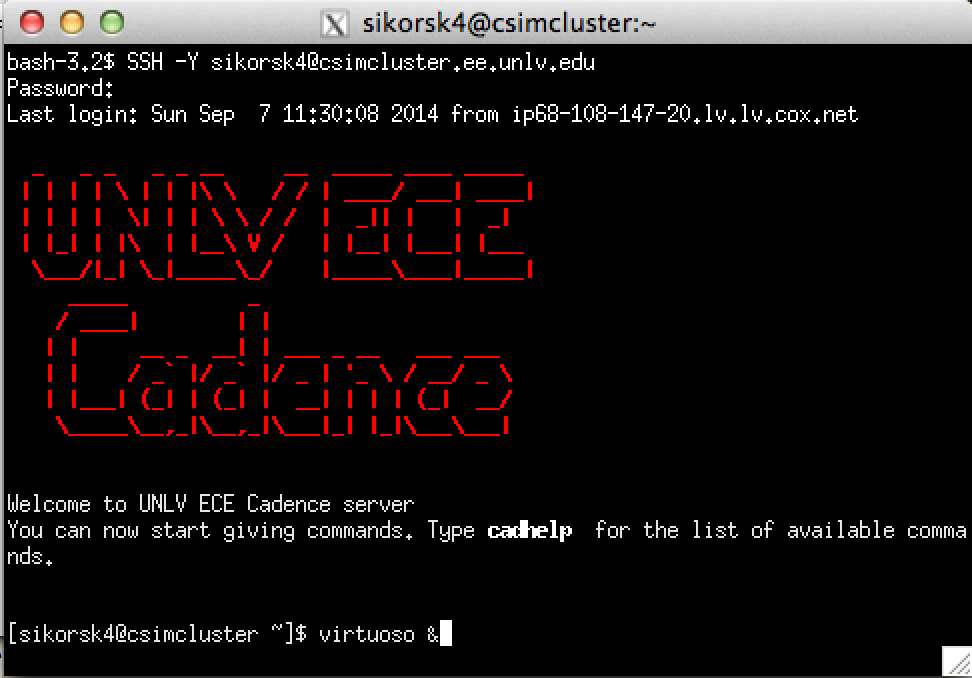
A new library was created, with a new Cell and Schematic.
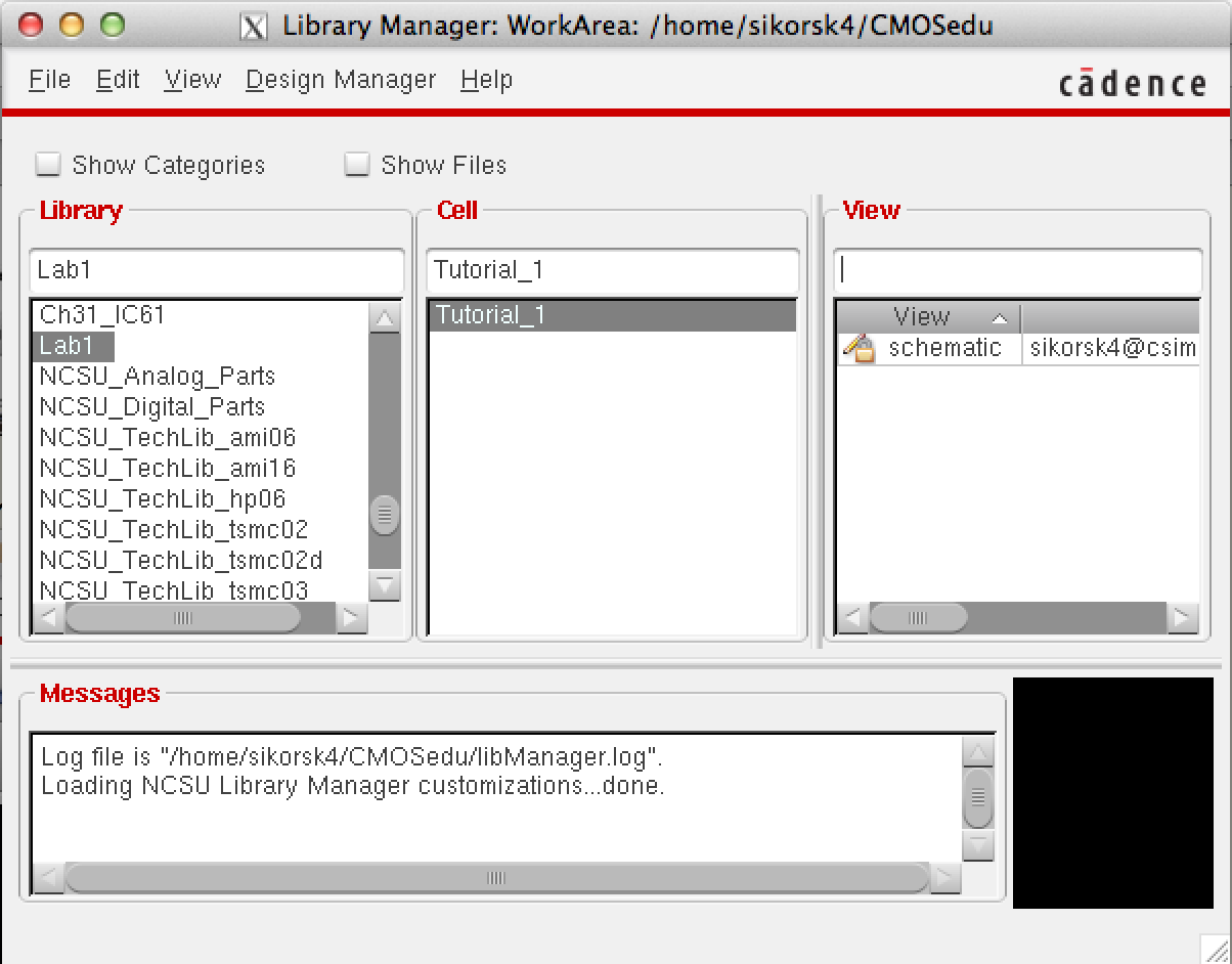
The schematic of a 1/2 voltage divder was created using 10k resistors.
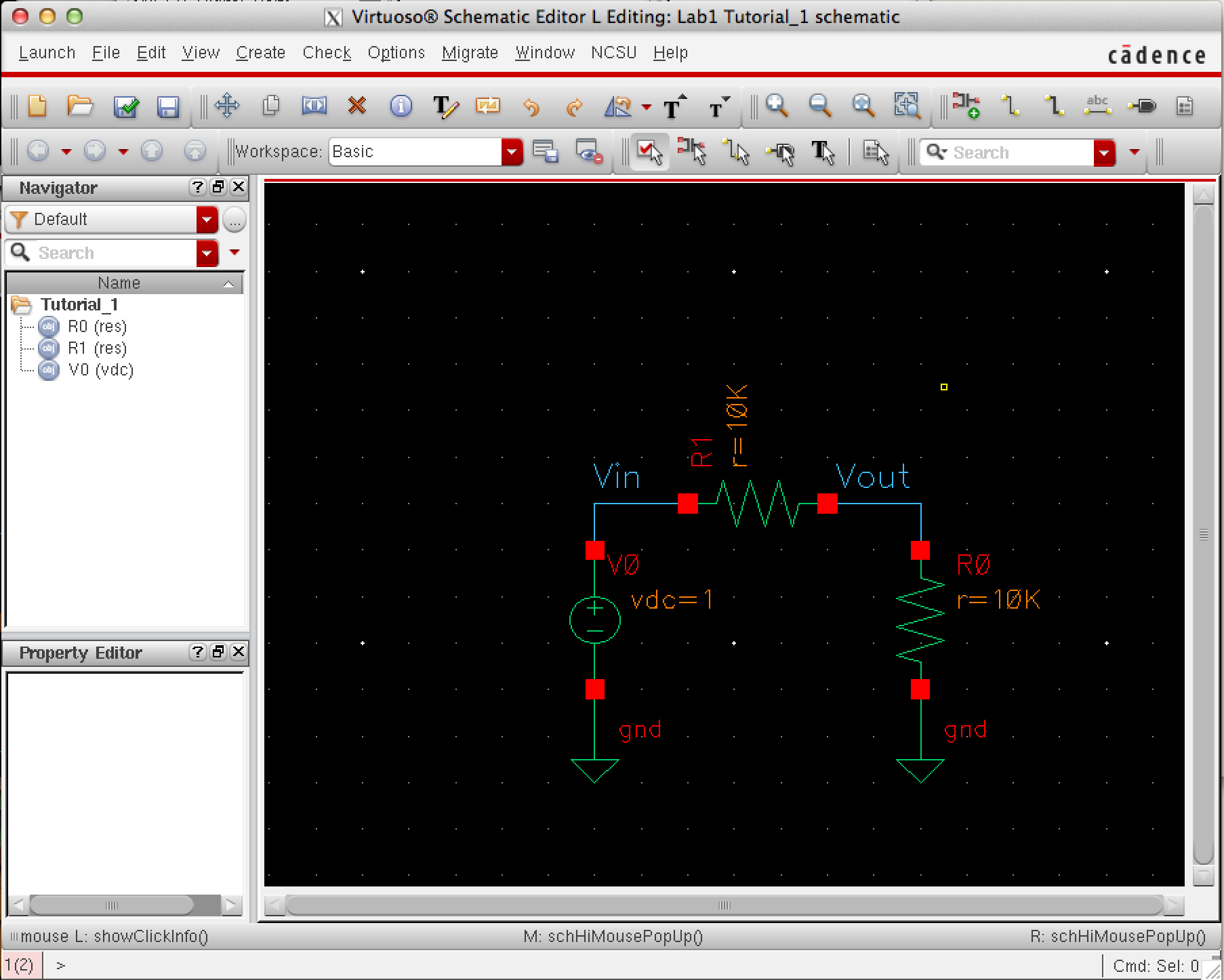
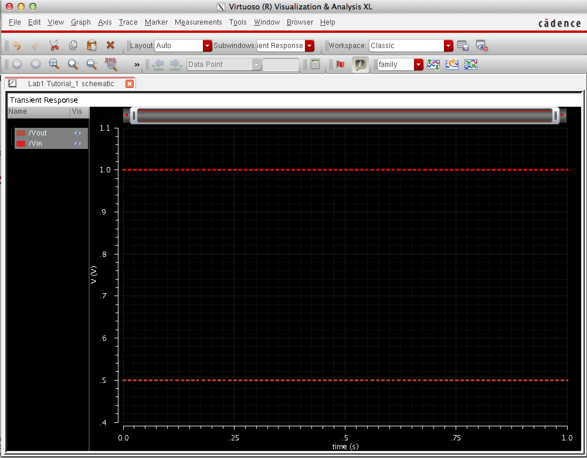
The schematic was simulated showing Vout = 1/2 Vin.
Return to EE 421L Labs