Lab 6 - EE 421L 

Authored by Gerald Lee

leeg28@unlv.nevada.edu

October 19, 2014


Design, layout, and simulation of a CMOS NAND gate, XOR gate, and Full-Adder


The objective of this lab is create shematics, layouts and simulations of a NAND, XOR and Full-Adder.


Logic Gate
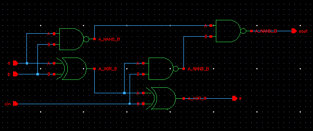
Schematic
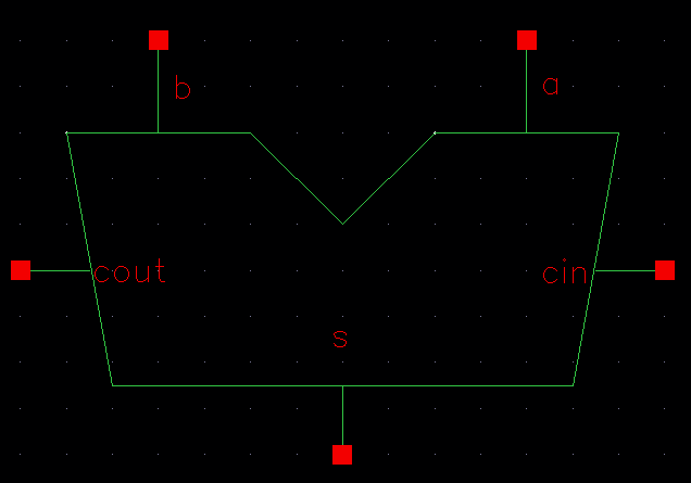
Symbol
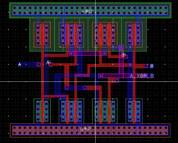
Layout
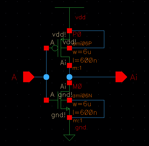
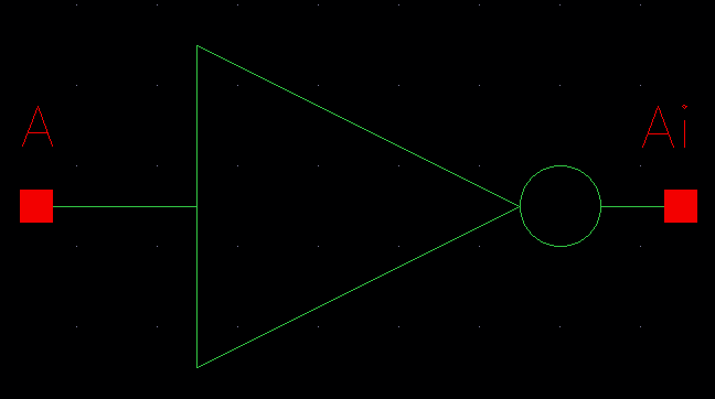
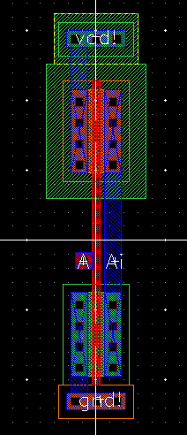
Inverter
http://cmosedu.com/jbaker/courses/ee421L/f14/students/leeg28/lab6/snip1.jpg
http://cmosedu.com/jbaker/courses/ee421L/f14/students/leeg28/lab6/snip2.jpg
http://cmosedu.com/jbaker/courses/ee421L/f14/students/leeg28/lab6/snip3.jpg
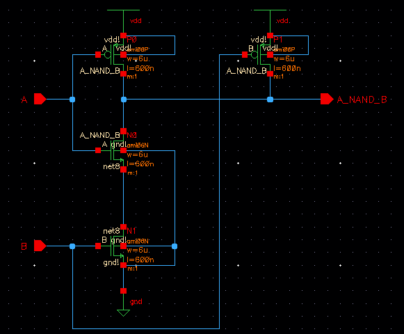
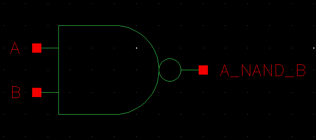
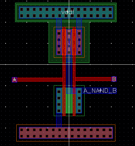
Nand
http://cmosedu.com/jbaker/courses/ee421L/f14/students/leeg28/lab6/snip4.jpg
http://cmosedu.com/jbaker/courses/ee421L/f14/students/leeg28/lab6/snip5.jpg
http://cmosedu.com/jbaker/courses/ee421L/f14/students/leeg28/lab6/snip6.jpg
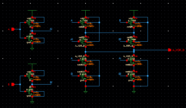
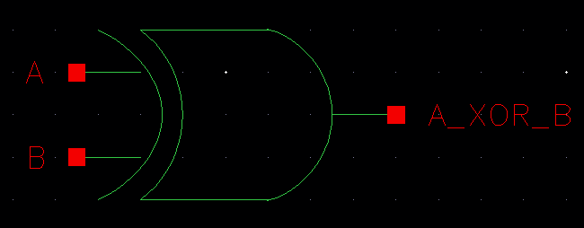
Xor
http://cmosedu.com/jbaker/courses/ee421L/f14/students/leeg28/lab6/snip7.jpg
http://cmosedu.com/jbaker/courses/ee421L/f14/students/leeg28/lab6/snip8.jpg
http://cmosedu.com/jbaker/courses/ee421L/f14/students/leeg28/lab6/snip9.jpg
Full-Adder
http://cmosedu.com/jbaker/courses/ee421L/f14/students/leeg28/lab6/snip14.jpg
http://cmosedu.com/jbaker/courses/ee421L/f14/students/leeg28/lab6/snip15.jpg


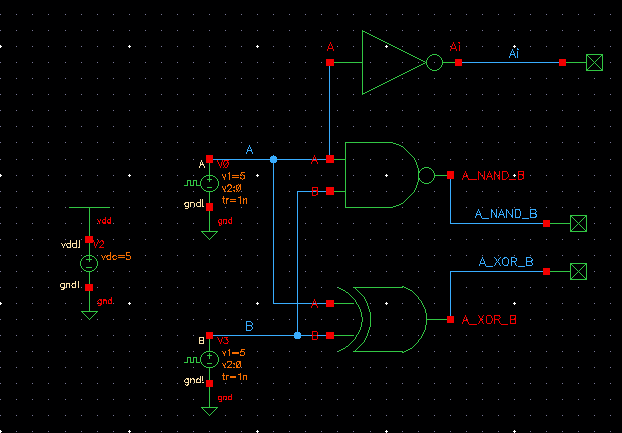
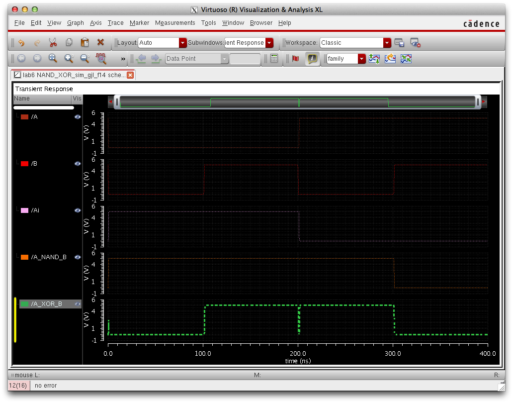
Simulating the Gates


http://cmosedu.com/jbaker/courses/ee421L/f14/students/leeg28/lab6/snip10.jpg


http://cmosedu.com/jbaker/courses/ee421L/f14/students/leeg28/lab6/snip11.jpg


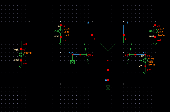
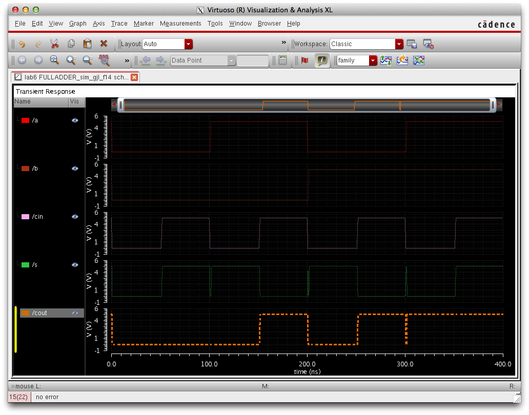
Simulating the Full-Adder


http://cmosedu.com/jbaker/courses/ee421L/f14/students/leeg28/lab6/snip12.jpg


http://cmosedu.com/jbaker/courses/ee421L/f14/students/leeg28/lab6/snip13.jpg

Here are the simulations for the full adder, notice the blips due to the timing delay of our signals this is due to the rise and fall time of the input signal.


Back-Up shown below.
http://cmosedu.com/jbaker/courses/ee421L/f14/students/leeg28/lab6/snip16.jpg


Design Files can be found here.