EE
421L Lab 1
Authored
By Alan Fortes
on August 6, 2013
fortesa@unlv.nevada.edu
The
following lab will explain the steps necessary to implement the NCSU
Cadence Design Kit, followed by the
design and simulation of a voltage divider.
First, download the NCSU
Cadence Design Kit, version 1.6.0 beta, found here: http://www.eda.ncsu.edu/wiki/NCSU_CDK
After clicking
the link above, click download, located at the right of the page, and follow all the necessary steps.
After
typing in your UNLV email and clicking REGISTER, you
should receive this email:
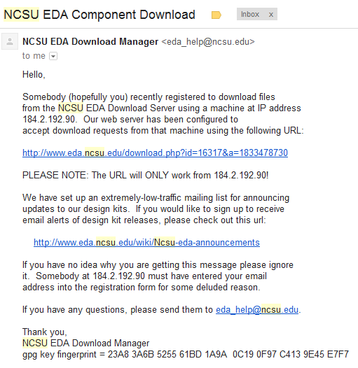
The
first
url in your email will lead you to a webpage, which will allow you to download
the NCSU
Cadence Design Kit
(CDK) version 1.6.0 beta.
After downloading the
compressed file, extract the contents
to your desktop.
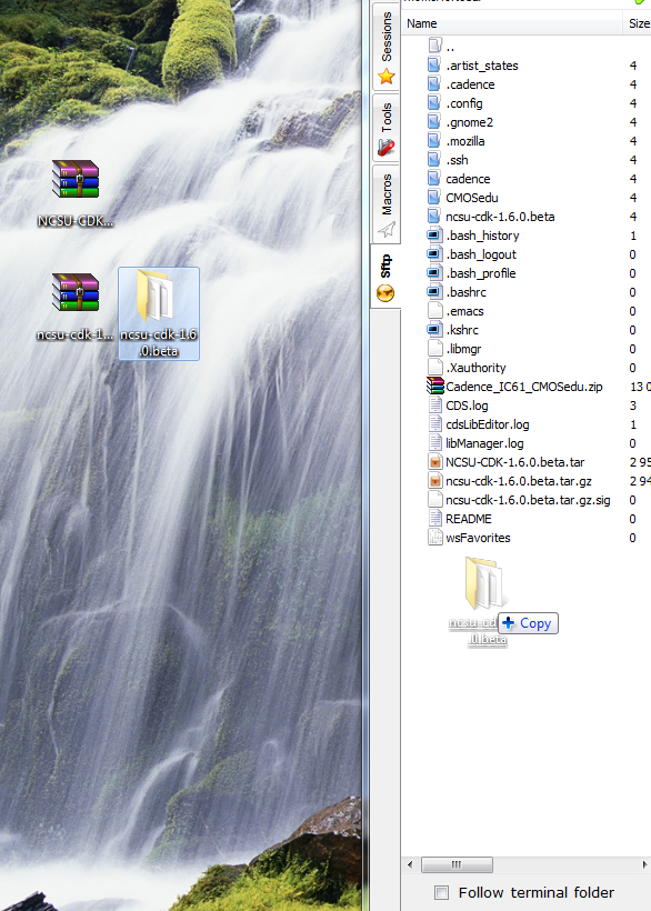
This will place
another compressed file called ncsu-cdk-1.6.0.beta.tar.gz on your
desktop. Extract the contents
of that compressed file onto the desktop, the same way your
did the first compressed file.
Doing that will place a folder called ncsu-cdk-1.6.0.beta on yourdesktop.
Drag and drop that
folder into your home directory on the csimcluster
server, like so:
Open
the .bashrc file in your home directory, and add these lines to the
end:
export SPECTRE_DEFAULTS=-E
export CDS_Netlisting_Mode=Analog
export CDS_LOAD_ENV=CWDElseHome
export
CDK_DIR=$HOME/ncsu-cdk-1.6.0.beta
Make sure that you view hiddien files, if you can't see the .bashrc file.
After having done that, type the following command:
. .bashrc
That's simply typing in a period, a space, another period and bashrc.
Now, make a folder in your home directory called CMOSedu. The command is:
mkdir CMOSedu
Copy the entire contents of $HOME/ncsu-cdk-1.6.0.beta/cdssetup
into the CMOSedu
folder, $HOME/CMOSedu.
The command for this is:
cp -a $HOME/ncsu-cdk-1.6.0.beta/cdssetup/. $HOME/CMOSedu/
Move into your CMOSedu directory, the command being CD CMOSedu, and rename the files cdsinit,
simrc,
and
cdsenv
to
.cdsinit,
.simrc,
and .cdsenv.
This is simply adding
a period in front of all of the files' names.
After you've done that, open the cds.lib file, and add these lines to
the file:
DEFINE analogLib /usr/cadence/IC615/tools.lnx86/dfII/etc/cdslib/artist/analogLib
DEFINE functional /usr/cadence/IC615/tools.lnx86/dfII/etc/cdslib/artist/functional
DEFINE sbaLib /usr/cadence/IC615/tools.lnx86/dfII/etc/cdslib/artist/sbaLib
The variant of "spice" that cadence uses is spectre for the
simulations. To ensure that our program uses this, add this line to the
end of your .cdsinit file:
envSetVal("asimenv.startup"
"simulator" 'string "spectre")
In the directory $HOME/ncsu-cdk-1.6.0.beta/lib/NCSU_TechLib_ami06,
there
are 3 bugged file that must be replaced.
First, delete these files from the aforementioned directory:
divaDRC.rul, divaEXT.rul,
and divaLVS.rul.
Save this zip file, diva_rul_files.zip, and transfer the
contents to that directory. Now that that is all done, we can run the program.
From the CMOSedu folder, run the following command: virtuoso
&
Running
the virtuoso & command will bring up this window:
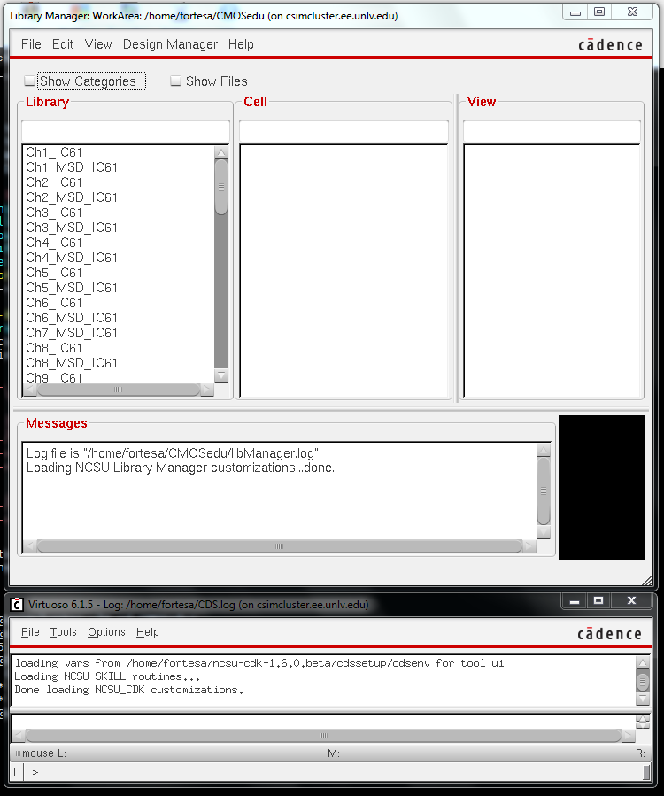
This
window is known as the library manager. Select
the Library option frome the File and New tabs. This
will allow us to create a new work space to create
a
voltage divider.
After
selecting Library, the follwing window will appear:
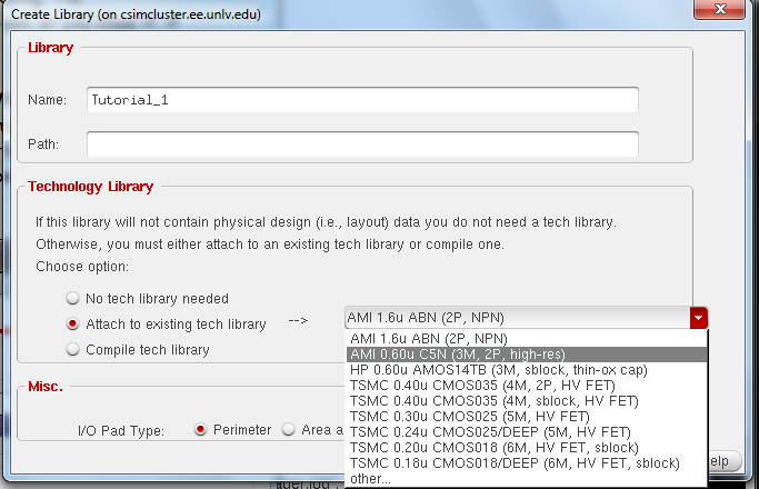
Type
in as the library name Tutorial 1, select the radio button labeled
Attach to existing tech library, and
select from the drop down list AMI 0.60u
C5N.
After doing all that
and clicking OK, head back to the library manager. At the library
manager, scroll down the library window, and select
the Tutorial_1 libary.
Click file, new, and cell view. This will bring up the following window:
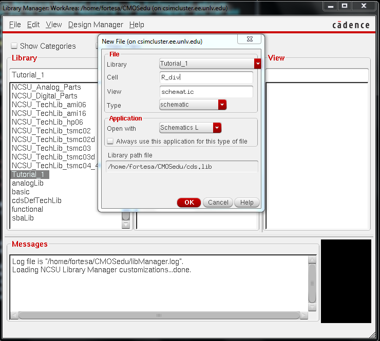
Enter
in the information as shown and click OK. The schematic construction
window should
pop up as a window with a black backgroud.
After
the window has come up, press the i key, or click the highlighted
button to bring up the Component
Browser and Add Instance windows. The component browser searches for
the piece
to the add to the schematic window and the add instance window adjusts
the properties. In
the component browser, select from the library drop down menu
NCSU_Analog_Parts, followed
by the R_L_C label in the white window. After making those selections,
select the
res label in the white window. In the add instance window, select the
resistance text box,
and enter in 10K Ohms.

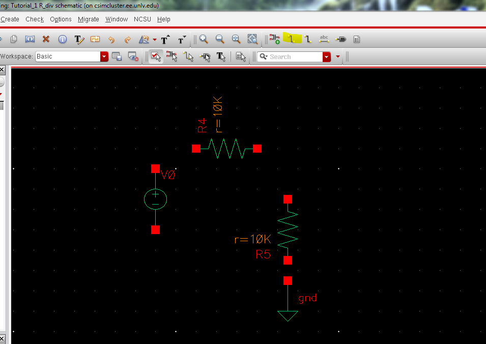
Hide
the add instance window and click on the black backgroud to add the
first resistor. To
rotate a component, press the right mouse button. To gain a closer view
of your schematic, press
the f button. To change the properties of an object, select the object
and press q.
After laying down the two resistors like so,

go back to the component
browser, click go up 1 level and select supply
nets, and gnd. place the ground symbol just below the vertical resistor.
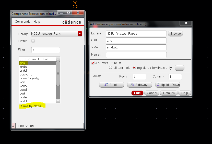
Click Go up 1 level and
select Voltage_Sources, and vdc. In the add instance window, place a 1 as the DC voltage.

Place the voltage source
symbol under, and to the left of the
horizontal resistor. Your end result will be like this:
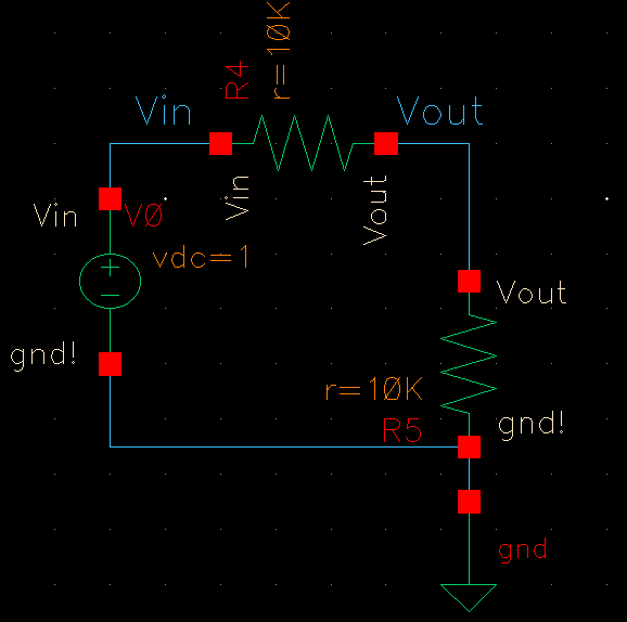
Connect the red
terminals with wire, accessable through the highlighted button up
above, or with the w key. This will yield the following:
Label the schematic's in
and out wires by pressing the L key and
entering
in Vin into the empty line in the new window and clicking the top left
wire.
Do the same thing, but instead of Vin, type Vout, and click the top
right wire.
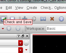
After the circuit
schematic is complete, click the check and save button up to to verify the circuit will work properly.
After the
circuit has been compiled and has been saved, click Launch, and ADE L.
This will bring
up the Virtuoso Analog Design Environment, as seen
below. If you have not set spectre to be your simulator, ensure it is so by
selecting setup and Simulator/Directory/Host.
Ensure that
spectre is your simulator.
After you have
done that, click the button one the right panel labeled AC DC TRans,
and select your tran as your analysis type, with your stop your time as
1.
After
that has
been done, click OK and select outputs, to be plotted, and select on
schematic.
Click on the Vin
wire, followed by the Vout wire. The wire's should be high lighted like so:
The Analog
Design Environment will look like the following after all that you've done:
Before you are
actually capable of running the simulation, you must first save the
state of what you have done so far. This is done by selecting session
at the top, then save state. Clicking these will bring up:
Be
sure to click cell view, then OK. Select in the Analog Design
Environment, session, and load state. Press the green play button and
soon the simulation window will come up.
Backing
up My Labs.
In
order to ensure that my hard work doesn't vanish for eternity, leaving
me to redo the whole of my labor, I frequently back up my labs,
projects, and anything else worthy of duplication.
This is
done by taking the folder containing my finished work, labeling it an
appropriate name, along with the date, placing it in a zip file, and
email that zipped folder to myself.
Contents of the file to be zipped:
Creating a zip
file:
Transfering the
folder to be backed up to the zipfile:
Emailing the
file to myself:
The end result,
stored in my email:


