EE 421L Project
Design, layout, and simulate an 8-bit ALU that can perform: A AND B, A OR B, A+B(addition), and A-B(subtraction).
Authored
by: Adam James Wolverton
Email: Wolvert9@unlv.nevada.edu
Today's
date: November 20th, 2013
Project description:
First half
of the project(no layout), a jelib of your design and an html report
detailing operation (including simulations), is due at the beinning of
lab on Nov. 8. The top level ALU icon used for simulations should have
the following inputs (all bus connections): A (8-bits), B(8-bits),
F(2-bits), and Z(8-bits). Ensure that you have input vectors saved for
simulations . Put your report (proj.htm) in a folder called /proj in
your directory at CMOSedu.
Second half
of the project will be a verified layout and documentation (in html),
is due at the beginning of lab on Nov. 22. Finishing the projects by
Nov. 22 will give us time to assemble chips for fabrication through
MOSIS.
First Half:
In
this portion we combine all of the elements necessary to make an ALU,
such as a Full adder, an arrays of OR and AND gates, and Multiplexers.
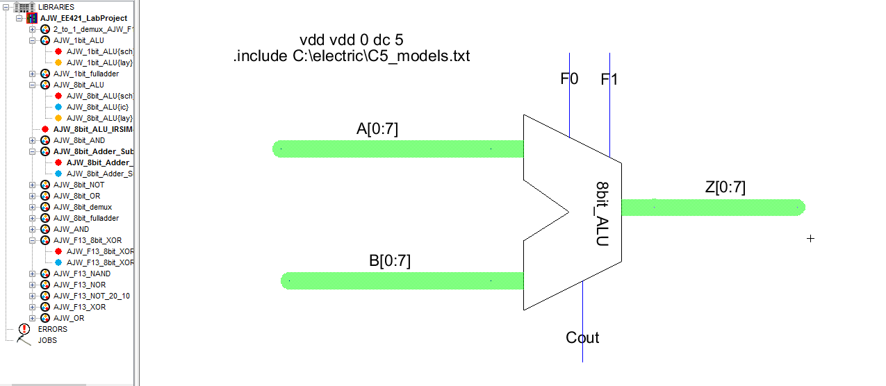
As seen below, this is my implementation of an 8-bit ALU. The way I set up the 8 bit buses, please NOTE that the Most Significant Bit (MSB) is the 7th bit and the Least Significant Bit (LSB) is the 0th bit. Note that I made an icon for implementation of a Full Adder/Subtractor.

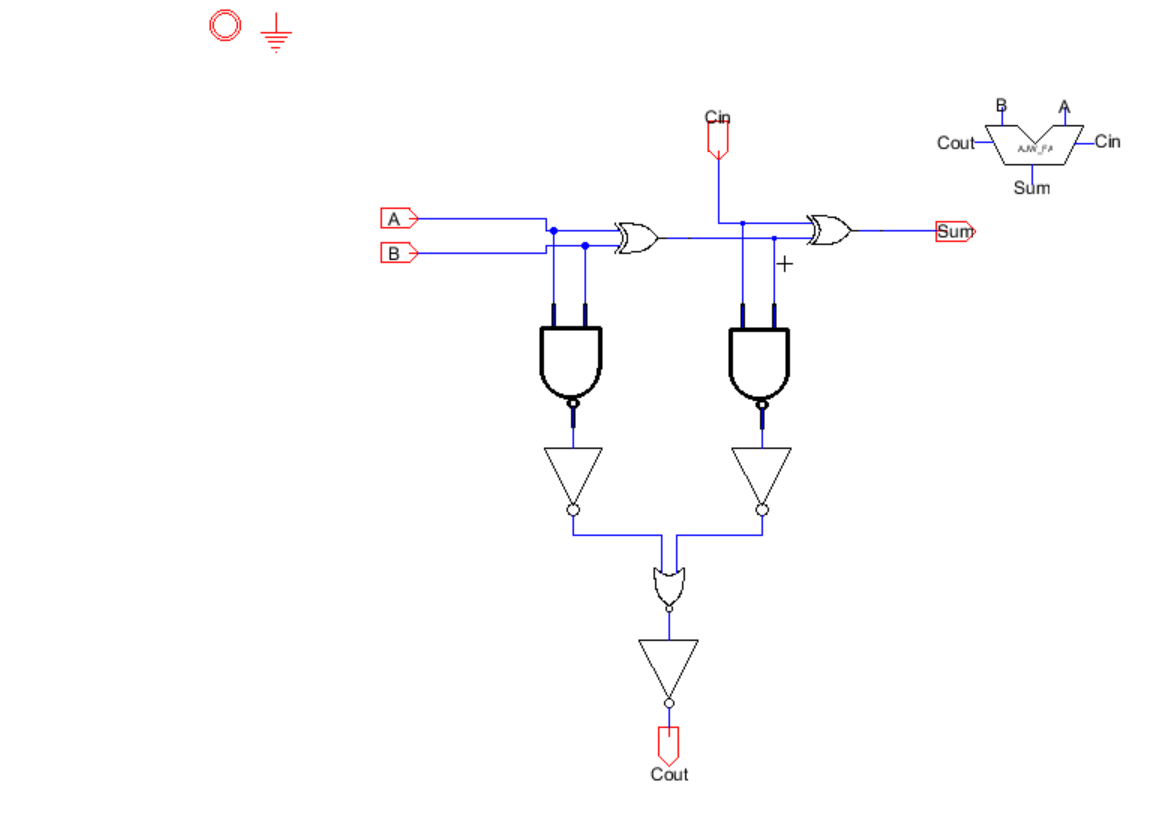
Here
is what is implemented in my 8 bit full adder/subtractor. I had noticed
that a ton of people, if not everyone was using an inverter and an
extra Demux to implement subtraction. I wanted to be different and try
my chances using an XOR gate to use the control input F0 to accomplish
subtraction. In order to accomplish subtration we must have A-B =
A+(-B)=AtB*+1. In order to perform the 2's complement, we will set the
initial carry-in to 1 instead of 0, which will add an extra 1 to the
sum. In conclusion, when F0 = 0 this will have the
Adder/subtractor perform addition, and when F1 =1 this will have it
perform the subtraction operation.

The overall control operation for my 8-bit ALU is as seen below:
| F1 F0 | Operation |
| 0 0 | Addition |
| 0 1 | Subtraction |
| 1 0 | OR |
| 1 1 | AND |
Here are my simulations using the icon I made for the ALU and IRSIM and LTSpice of my 8-bit ALU to ensure it is operating correctly:
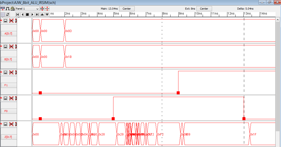

Observing
the above IRSIM simulation of my 8-bit ALU you can see that it is
working correctly for the chosen values of A = 0x0D (=0000 1101 in
binary) and B = 0x1B (= 0001 1011 in binary).
When (F1,F0)=(0,0), we get the correct addition value of A+B = 0x0D + 0x1B = 0x28
When (F1,F0)=(0,1), we get the correct subtraction value of A-B = 0x0D - 0x1B = 0xF2
When (F1,F0)=(1,1), we get the correct AND operation value of A AND B = 0x0D AND 0x1B = 0x09
When (F1,F0)=(1,0), we get the correct OR operation value of A OR B = 0x0D OR 0x1B = 0x1F
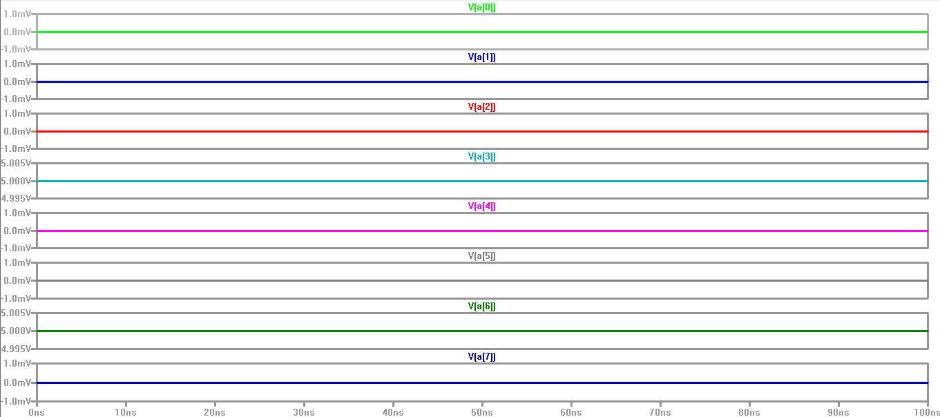
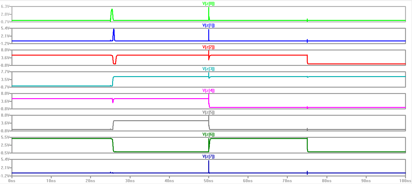
Below is the simulation of the operation of my 8-bit ALU using LTSpice:
Here are the Bits for A:
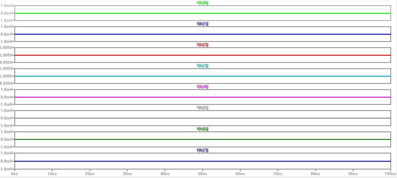
Here are the bits for B:
Here are the result bits for Z:
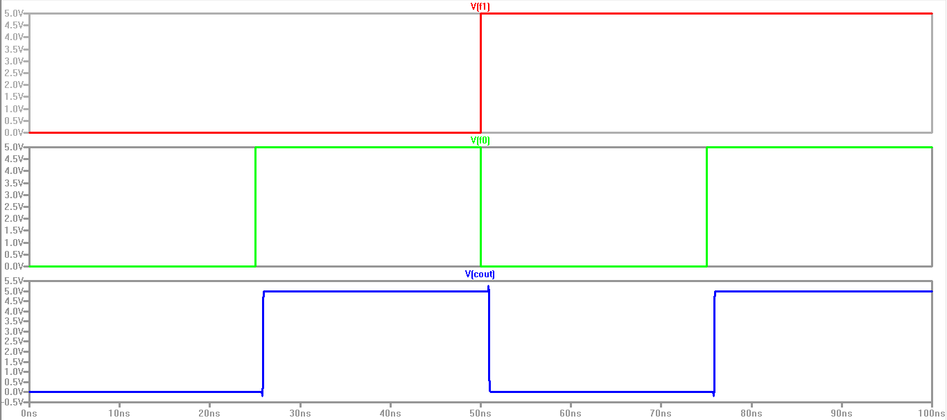
Here are the Control inputs F1 and F0, and the Carry out Cout:
Second Half:
In
this portion of the project we will proceed to designing the layout of
the 8-bit ALU after proper operation has been verified. In order to
make an 8-bit ALU, I decided to first design a simple 1-bit ALU then
cascade 8 of them together so that it can form an 8-bit ALU. Below, you
will find some "new" layouts that haven't been created in my propior
labs, which I implemented in the design of the layout for the 8-bit
ALU.
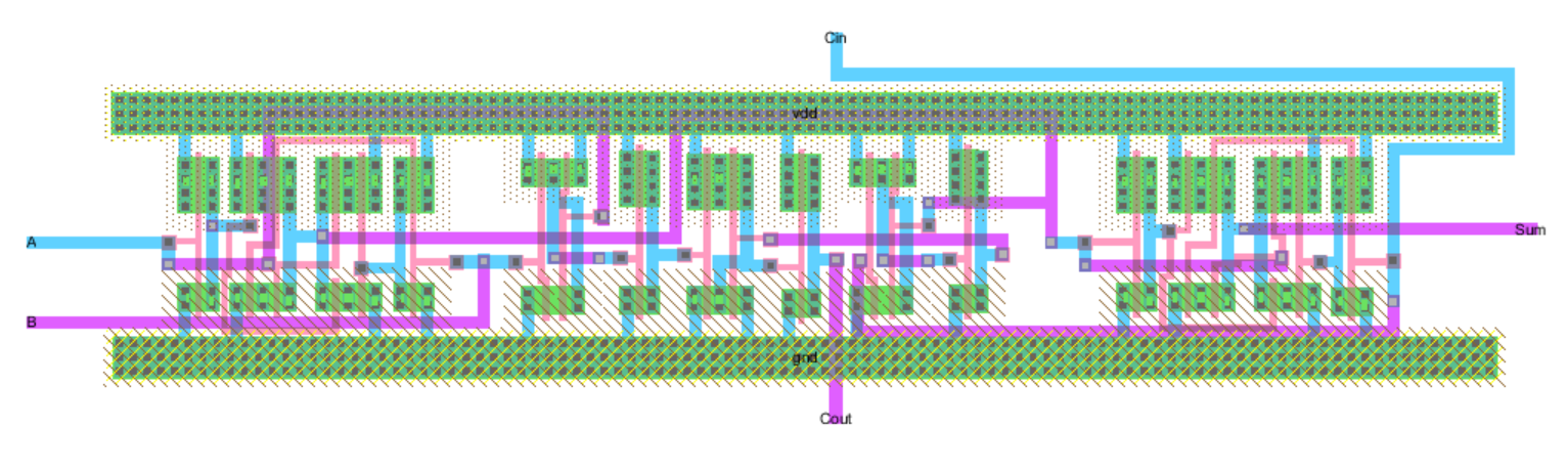
Here is the schematic and layout of a 1-bit Full Adder used in the 1-bit ALU.
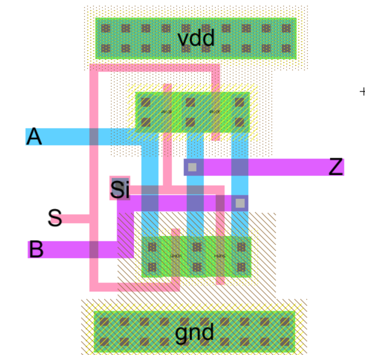
In
the previous lab, we were given the schematic of a 2-to-1 Demux, but we
weren't not given a layout, so I made the layout to be used in my 8-bit
ALU. In the ALU itself, I used an inverter between S and Si to
accomplish only 1 control input.
Once
I made these layouts, I used them as well as previously created layouts
to put together the 1-bit ALU layout design shown below.

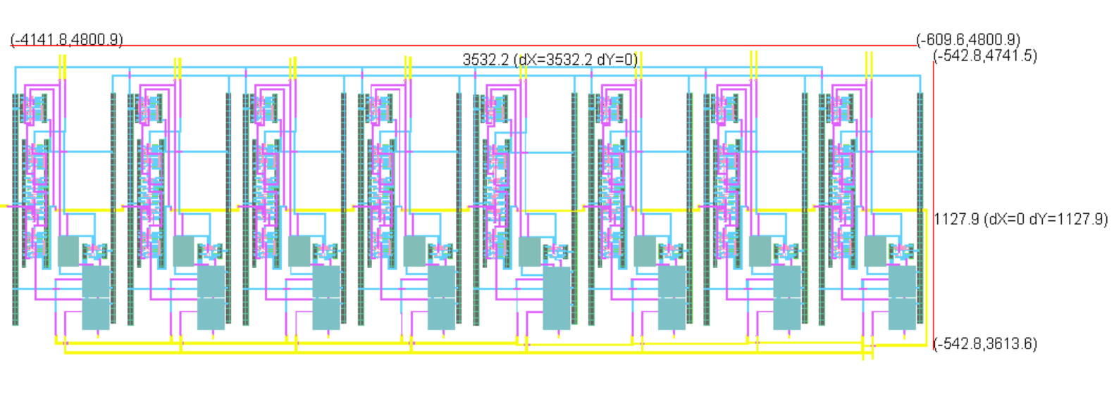
Cascading 8 of these 1-bit ALU layouts will give me an 8-bit ALU as shown below:
After the layout is completed, I backed up all of my work again as shown below:

To gain access to my Project Library for this 8-bit ALU right click and save HERE
To return to Adam's Lab directory click HERE