Lab Design Project, Part 1 - EE 421L
| Input (F) | Output (Z) |
| 00 | Z = A AND B |
| 01 | Z = A OR B |
| 10 | Z = A + B |
| 11 | A = A - B |
F[0] is least significant bit, or LSB.
F[1] is most significant bit of control signals (MSB).
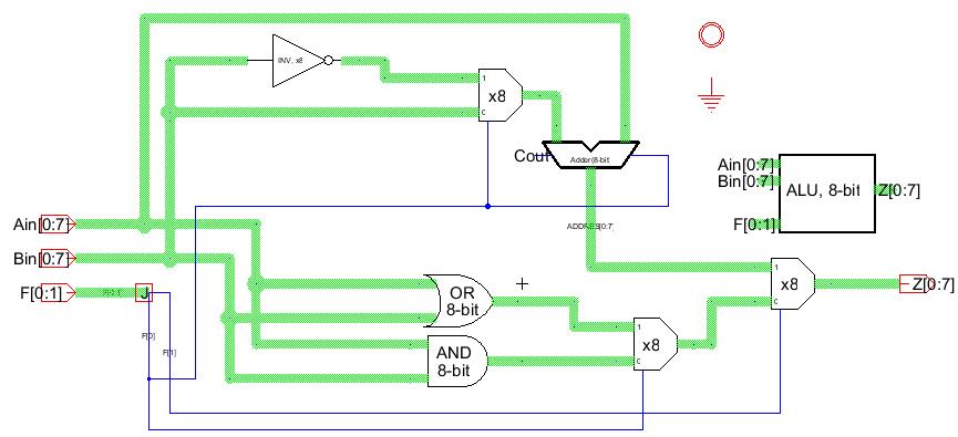
Operation of ALU:
The output of the ALU is selected by the control signals using the multiplexers
which were developed in an earlier lab. For example, if F[1] is low, the output of
the AND and OR gate section of the circuit is selected, depending on F[0] and
another multiplexor.
The addition and subtraction circuit was a little more complicated, but
actually works very well in practice. Addition is easy using the 8-bit adder
we built in another lab. Subtraction is implemented as adding A to the 2's
(or two's) complement of B. This is the equivalent of subtraction. The
implementation of this is surprisingly simple.
There are two steps required to get the 2's complement of a binary
number. First, invert the entire word, and then add 1. We have connected
a set of inverters to the B input bus. When F[0] is high, we switch this
inverted B bus through a multiplexer to the adder. (Subtraction occurs
when F[0] is high) The final thing we need is to add one to the addition,
which is equivalent to adding one to the B input, after inversion. Attaching
F[0] to the Carry In input of the adder solves this problem elegantly.
Below is the schematic of the circuit.
The IRSIM utility is now used to simulate this circuit. The input vector can be found here.
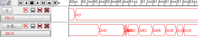
For our first set, A was chosen to be 0x33(decimal 51) and B was chosen to be 0x0D (13).
The first operation, AND, is seen below. The result is 0x01, as expected.
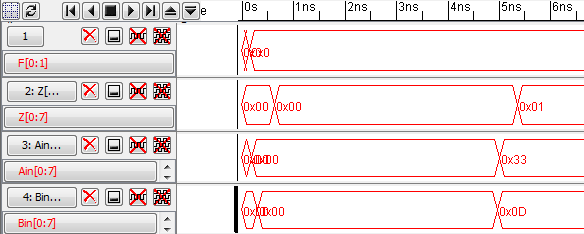
The OR function will be demonstrated on the second input sequence, but is available
in the input vector for viewing.
Next we add the two inputs (F = 10 = 0x2). The binary view would be:
0011 0011 + 0000 1101 = 0100 0000 = 0x40 = 64.
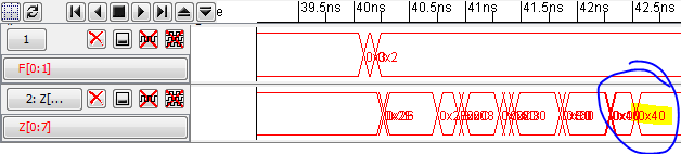
Subtraction is 51 - 13 = 38 or 0x26 in hexidecimal.
Binary: 2's complement of B = 0x0D = 0000 1101 is
1111 0011; Add 0011 0011 + 1111 0011 = 0010 0110 = 0x26 = 38.
At least the math works out!
Our second input test sequence is A = 0xCA, or -54 in 2's complement,
and B = 0x9F = -97. For AND, 1100 1010 AND 1001 1111 = 1000 1010 = 0x8A.
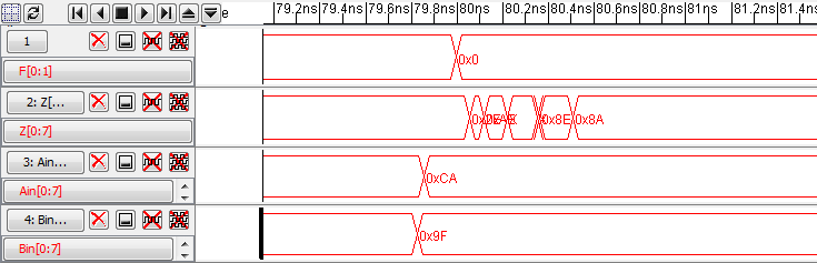
For OR, 1100 1010 OR 1001 1111 = 1101 1111 = 0xDF.
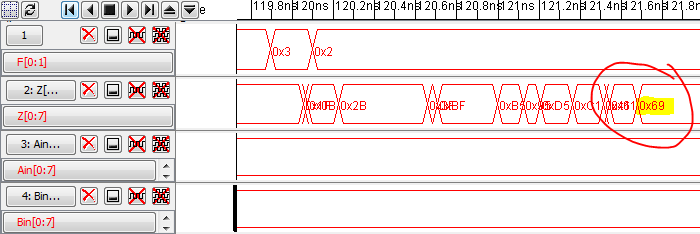
Addition is also simple: 1100 1010 + 1001 1111 = 0110 1001 = 0x69 = 105. Note
that there is an overflow with this computation, as adding two negative numbers
has produced a positive number.
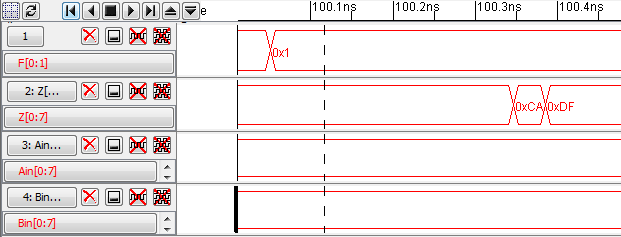
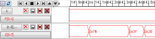
Finally, to perform subtraction, we find the 2's complement of 0x9F, which
is 0x61 = 0110 0001. Add to A: 1100 1010 + 0110 0001 = 0010 1011 = 0x2B = 43.
This is what we should expect from (-54) - (-97) = 43.
The .jelib file can be found here