Project - EE 421L
Authored
by: Medhanie Petros
E-mail: petrosm@unlv.nevada.edu
Date: 11/22/2013
Project description
design, layout, and simulate an 8-bit ALU that can perform: A AND B, A OR B, A + B (addition), and A - B (subtraction).
First half of the project
To design an ALU first you need to design AND, OR, DMUX, and Fulladder. For this project you can get all these designs from
previous
labs. You just need to do the layout part for each of them, and have to
fix DEMUX and the Fulladder (CLK for DMUX, Cin and Cout for Fulladder)
from 8 bus drive to single bus. The following figs. are some the layout and schematic of parts of the ALU.
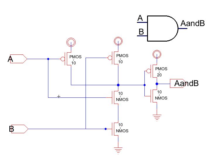
Single AND Schematic:
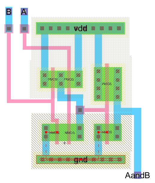
Single AND Layout:
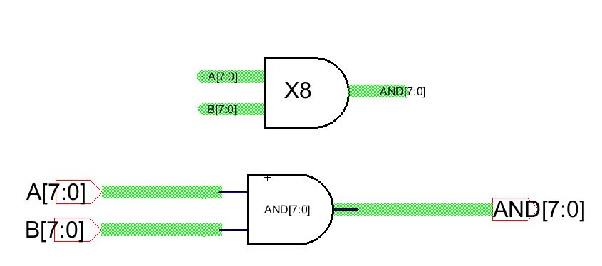
X8 AND Schematic:
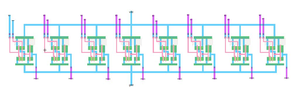
X8 AND Layout:
Single OR Schematic:
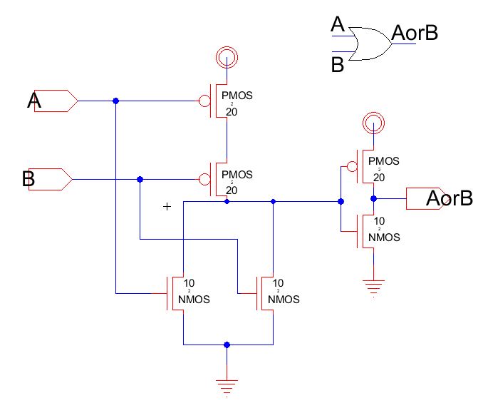
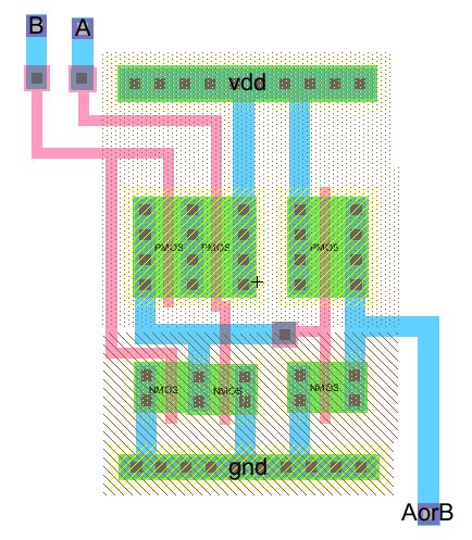
Single OR Layout:
X8 OR Schematic:
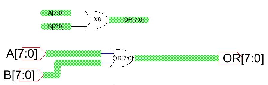
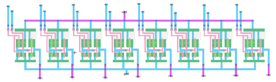
X8 OR Layout:
Single Invertor Schematic:
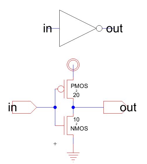
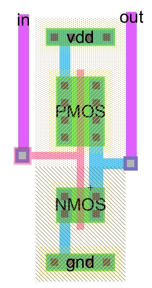
Single Invertor Layout:
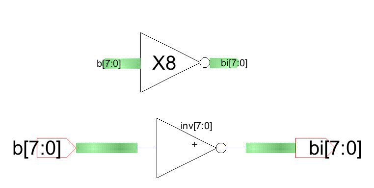
X8 Invertor Shcematic:
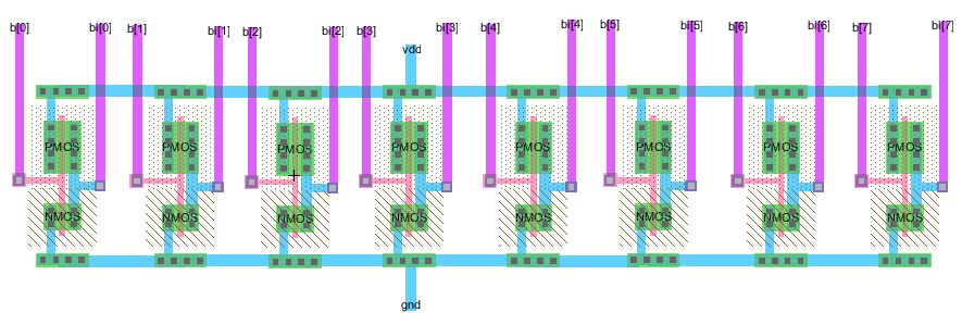
X8 Invertor Layout:
Single Fulladder Schematic:
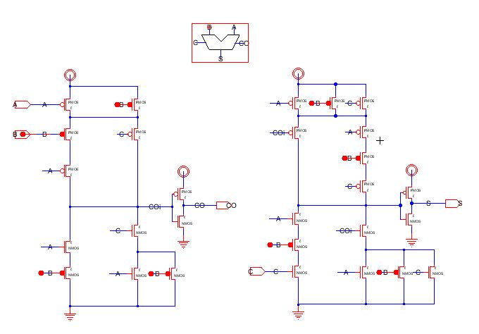
Single Fulladder Layout:
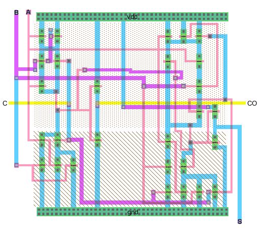
X8 Fulladder Schematic:
 X8 Fulladder Layout:
 Single Demux Schematic:
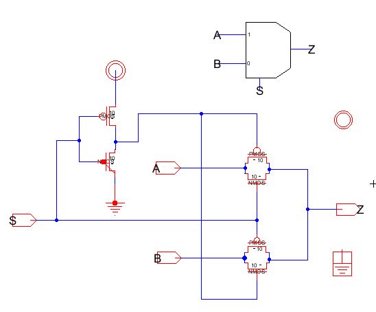
Single Demux Layout:
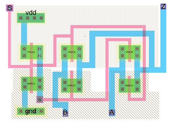
X8 Demux Schematic:
 X8 Demux Layout:
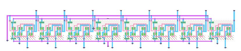
The ALU:
Now using the above components designed, you can make (design) the ALU.
After design, the ALU must perform the following teble.
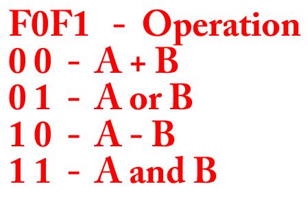
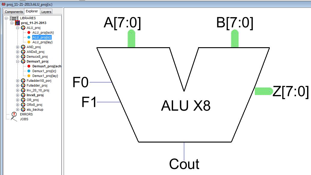
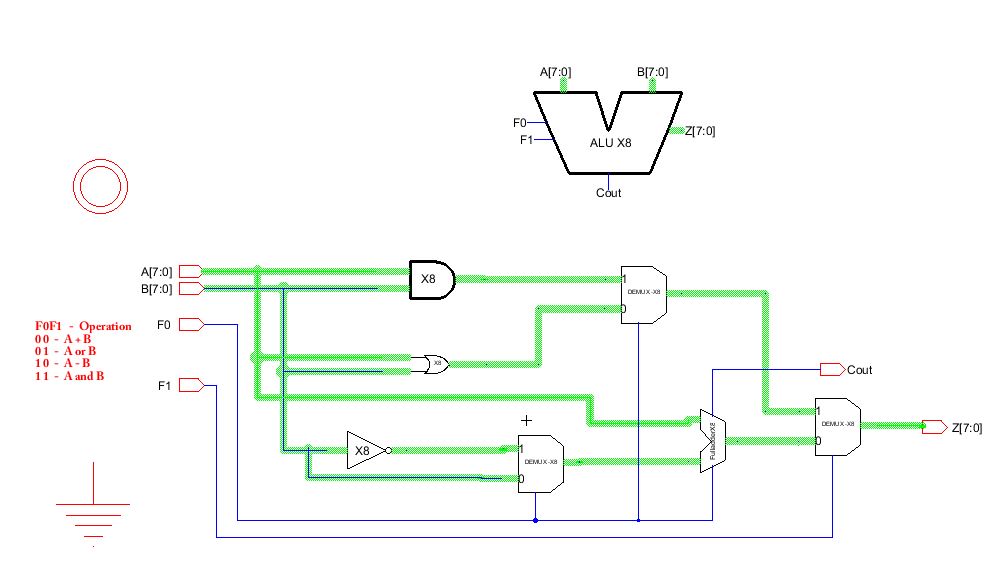
This fig are the Icon and Schematic for the above teble.
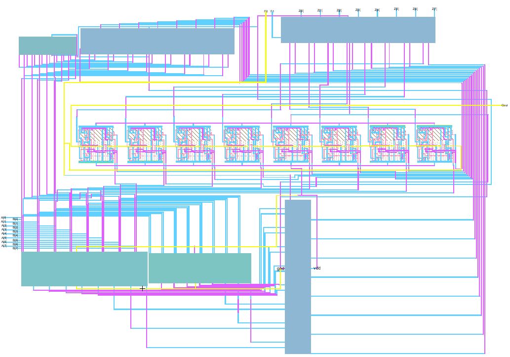
The Schematic of the ALU:
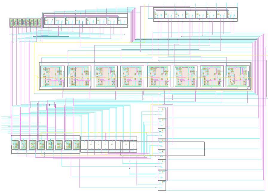
The Layout of the ALU:
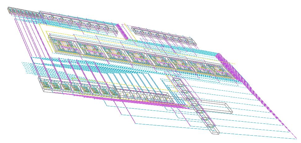
3D ALU front side view:
Check if there is an error when you done your layout and schematic of the ALU
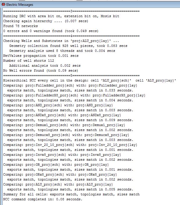
To
check if the above schematic and layout of the ALU are working, you need to calculate some
numbers using IRSIM,
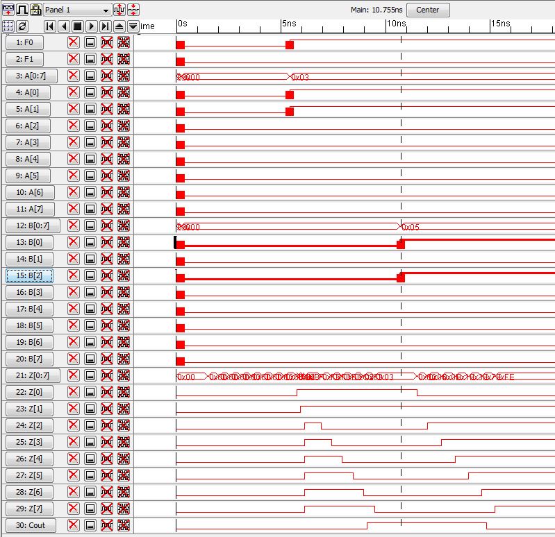
When F0 = high and F1 = gnd (which is 10), then SUBTRACTION function is called.
Say you want to subtract a number for example 3-5, then set for A = 0000 0011, and B = 0000 0101
for calculation, then you get the following IRSIM reasult, which is every output of Z goes to high except for Z0.
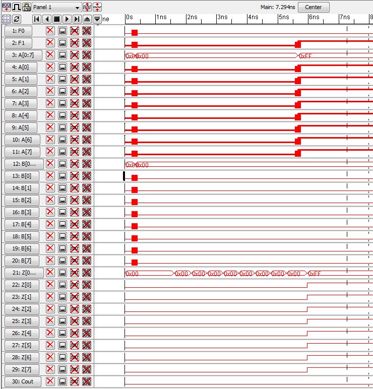
When F0 = gnd and F1 = high (which is 01), then OR function is called
For example
A = 1111 1111 or 255 and B = 0000 0000 or 0 , then you should get all Z's go to high as the following fig.
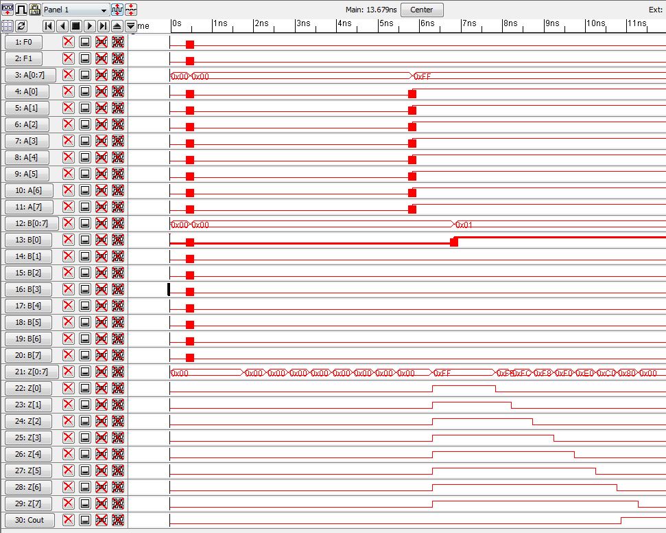
When F0 = gnd and F1 = gnd (which is 00), then ADDITION function is called
For example
A
= 1111 1111 or 255 and B = 0000 0001 or 1, then you should get all Z's
goes to low, and your carryout goes to high as the following fig.
Which the reasult is 1 0000 0000.
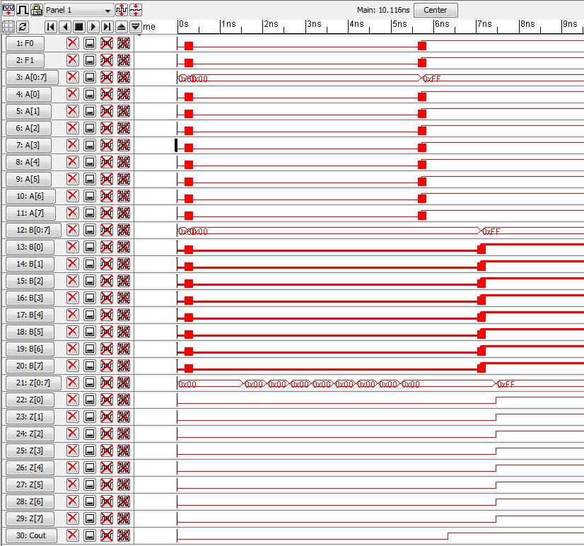
When F0 = high and F1 = high (which is 11), then AND function is called
For example
A
= 1111 1111 or 255 and B = 0000 0000 or 0, then you should get all Z's
goes to low,
and
A = 1111 1111 or 255 and B = 1111 1111 or 255, then you
should get all Z's goes to high as the following fig.
you can also perform suntraction
Backup the work zip it and email it to yourself.
.jelib file
Return to Labs
Return to students list