Lab 7 - Using buses and arrays in the design of word inverters, muxes, and high-speed adders
Authored by Nolan Moore
Date: November 1, 2013
Email: mooren14@unlv.nevada.edu
Lab 7 Directions
Lab 7 Working Library
Prelab:
N/A
Lab Procedure:
8-bit logic gates
For this section, we will be creating 8-bit versions of some of the logic gates we developed in lab 6 previously. We will be creating NAND, AND, NOR and OR gates, all of which will accept two 8-bit buses as inputs and output a single 8-bit bus.The format will be schematic and icon view of the 8-bit gate followed by a schematic used for simulation and the simulation results of the gate.
8-bit NAND gate
Schematic and Icon
Simulation schematic

Simulation

8-bit NOR gate
Schematic and Icon
Simulation schematic

Simulation

8-bit AND gate
Schematic and Icon
Simulation schematic

Simulation

8-bit OR gate
Schematic and Icon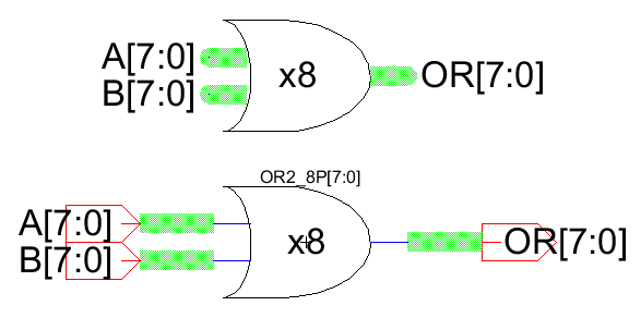
Simulation schematic

Simulation

8-bit gate testing
Here we have added each of the 4 8-bit gates we created and test them with a single set of A and B inputs.Schematic

2-to-1 MUX
Next we will create a 2-to-1 multiplexer. As seen below, the transistor design is fairly simple. The original MUX to be created had four inputs A, B, S and S' complement. Our design removes the need for S' as an input by including an inverter in the device.Schematic and Icon

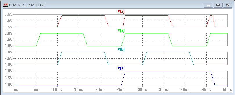
Simulation
The 8-bit version of the 2-to-1 MUX is below, followed by the simulation results.
8-bit Schematic and Icon

8-bit Simulation Schematic

8-bit Simulation

Full Adder design
Like the MUX we created, the full adder design will be built from transistors as the basis as well. This is different from the previous lab in which we used logic gates as the building blocks to create the full adder. A single bit full adder is shown followed by the simulation results.Single Schematic and Icon

Simulation
Next we have the 8-bit version of the full adder. The schematic and icon are presented first followed by the schematic to be used for simulation.
8-bit Schematic and Icon

8-bit Simulation Schematic

Unfortunately, I was unable to determine to means to properly simulate the 8-bit full adder circuit. I could not determine how to add the necessary signals to the simulation and as such I was unable to finish the simulations.
8-bit IRSIM Simulation

Full adder 2
Return Home