Lab 3 - ECE 421L
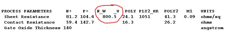
Given a sheet resistance of 800 ohms/square we can calculate the dimensions of the resistor. We want to solve
the following equation. 10K = 800*(L/W). W can't be any value. The minimum width is specified in the MOSIS
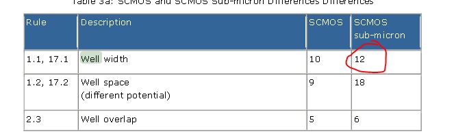
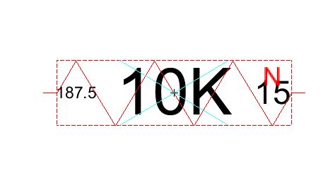
If we pick W to be 15 then L has to be 187.5.
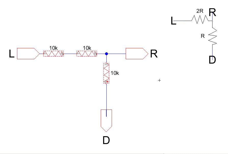
Proceed to create a schematic for this resistor.
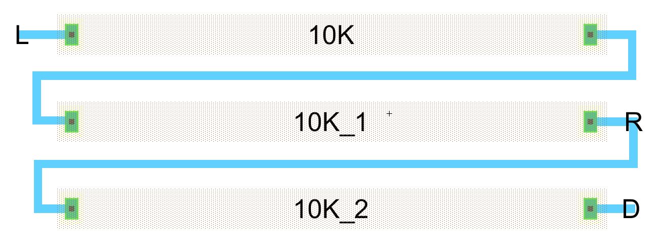
We can break up the DAC layout into smaller parts. First we eill layout one cell containing a small part of
the DAC. We can then copy this cell to make it easier. Create the following cell. The symbol can anything,
since it doesn't affect the schematic or layout.
Now, proceed to make the layout for this cell. Remember to make your resistors 15 by 187.5. Make sure you use the same exports.
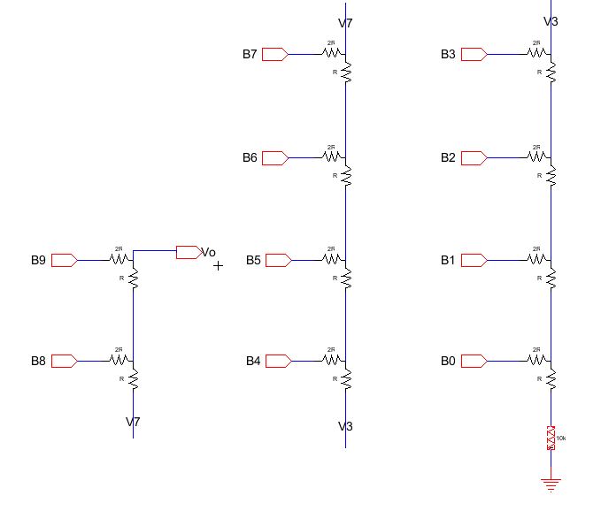
Make sure you DRC, NCC, and ERC your design. Now we can create the DAC using the schematic of the three resistors.
Don't forget to add the extra resistor at the end connected to ground.
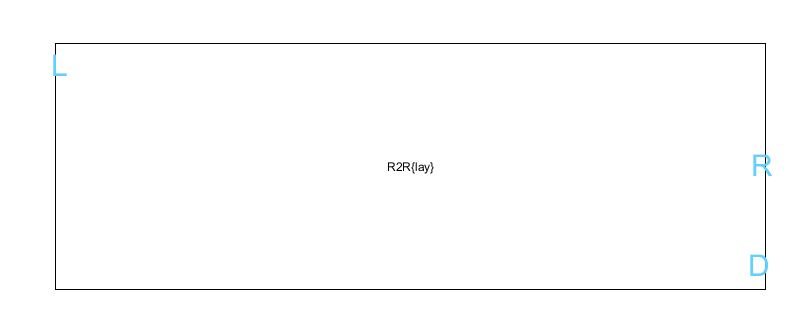
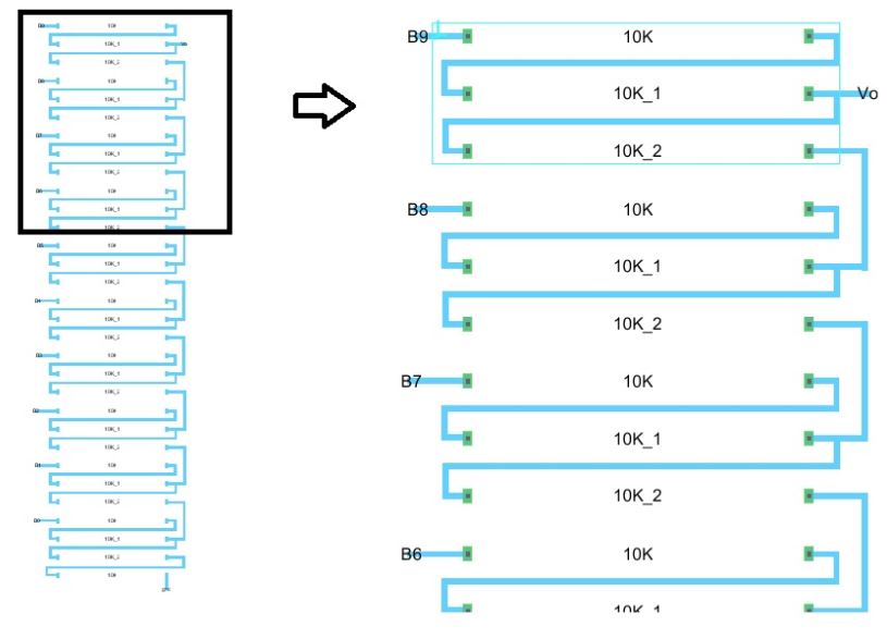
To make the layout for the DAC, we can copy the layout created earlier 10 times. Make sure you drag it instead of
using ctrl-C, so that it also copies the exports.
The copy should look like this.
To see the inside of it you can click on the eye icon.
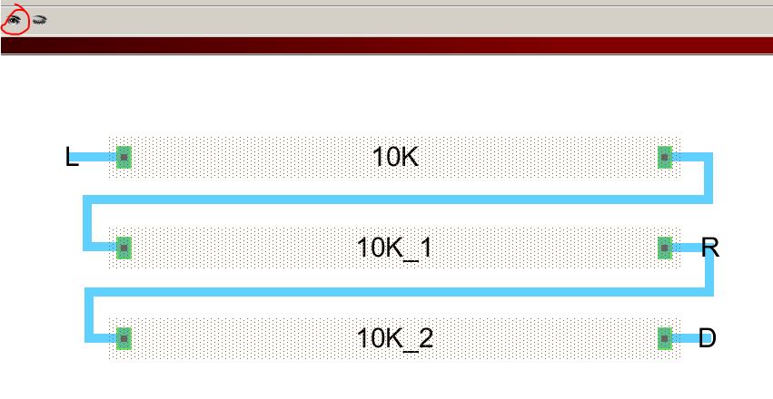
Now build the layout of the DAC using the smaller layout as a building block. Make sure to export the same nodes
that are on the schematic, and add the extra resistor.
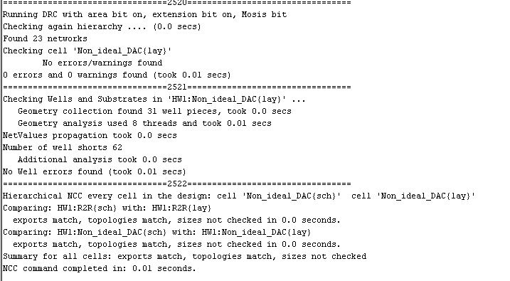
Make sure you DRC, NCC, and ERC your design. If you don't have any errors your dialog box should look like this.
 ADCDACsim.JPG
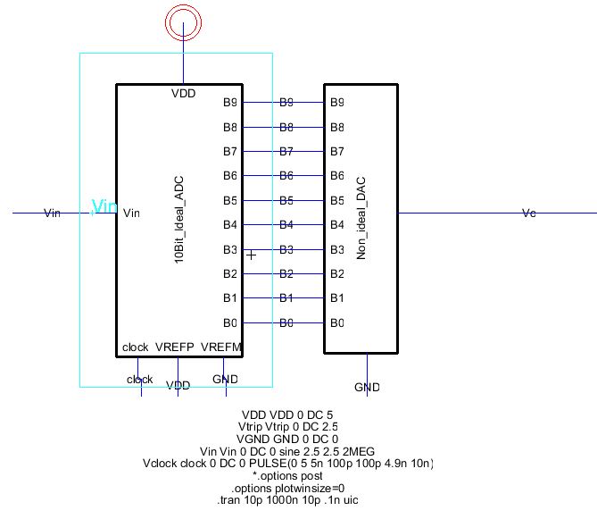
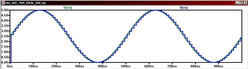
Finally, we can simulate the DAC to ensure correct operation.
Finally, back up your work.