Lab 1 - ECE 421L
Make sure to take screenshots or snip the corresponding images on your computer.
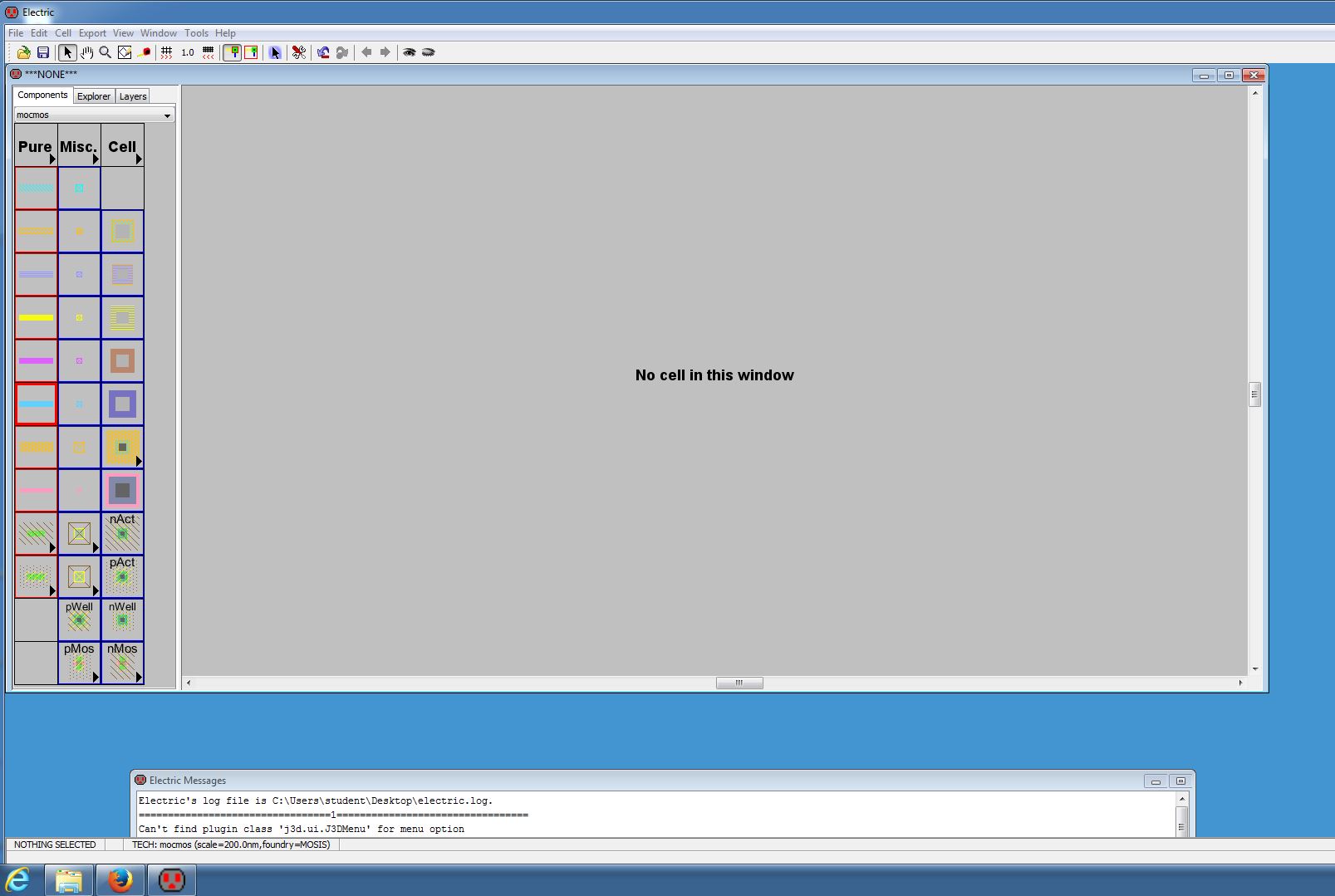
Step 1: Open Electric, make sure LTspice is installed, and its settings are correct in Electric.
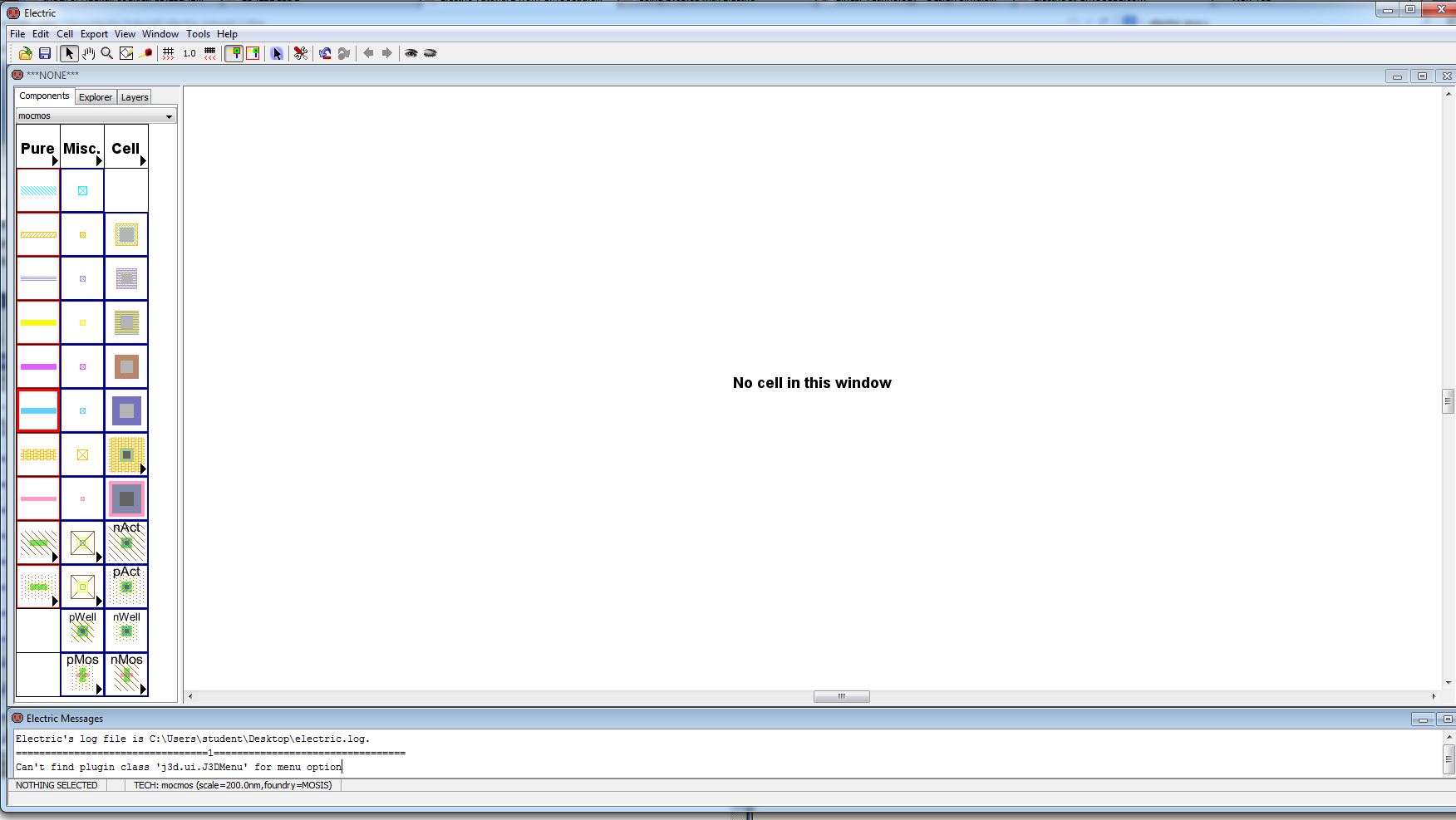
Step 2: Change the backgroud color to white by going to Window>Color Schemes>White Background Colors
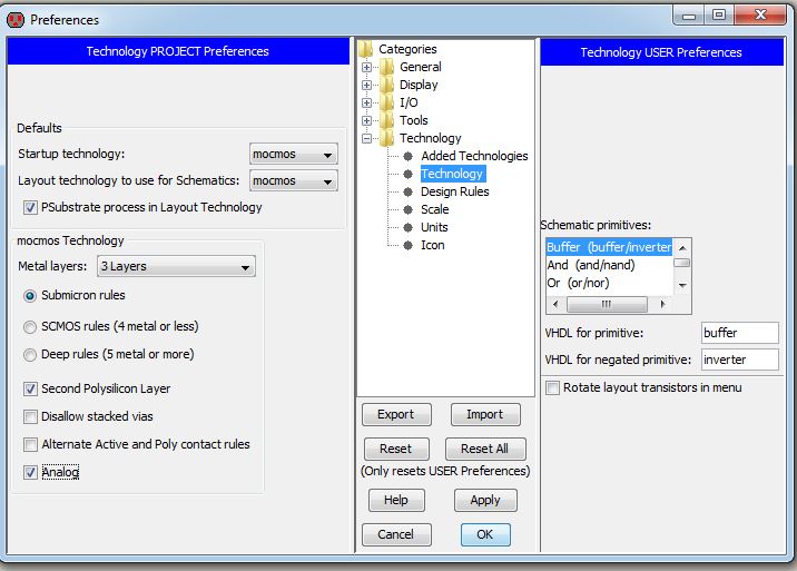
Step 3: Change settings to use C5 process by going to Preferences. Then go to Technology>Technology and copy the settings below.
Step 4:Change the Scale by going to Technology>Scale and copy the settings below.
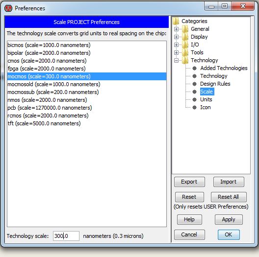
Click Ok and Select Mark All Libraries on the prompt.
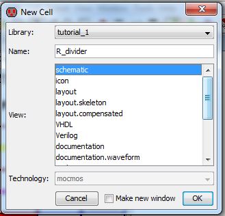
Step 5: Create a new schematic by going to Cell>New Cell. Use the settings below and then click ok.
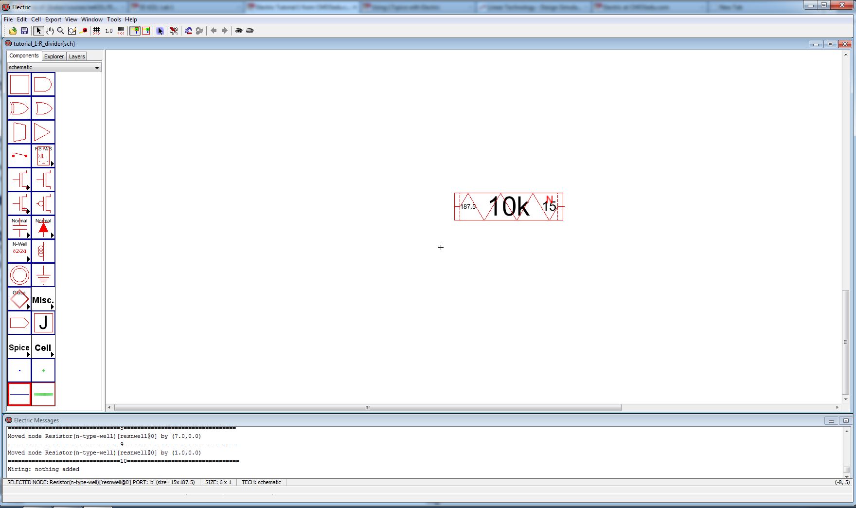
Step 6:There will be a list of components on the left click on the arrow on the resistor, select N-Well, and place the resistor on the schematic.
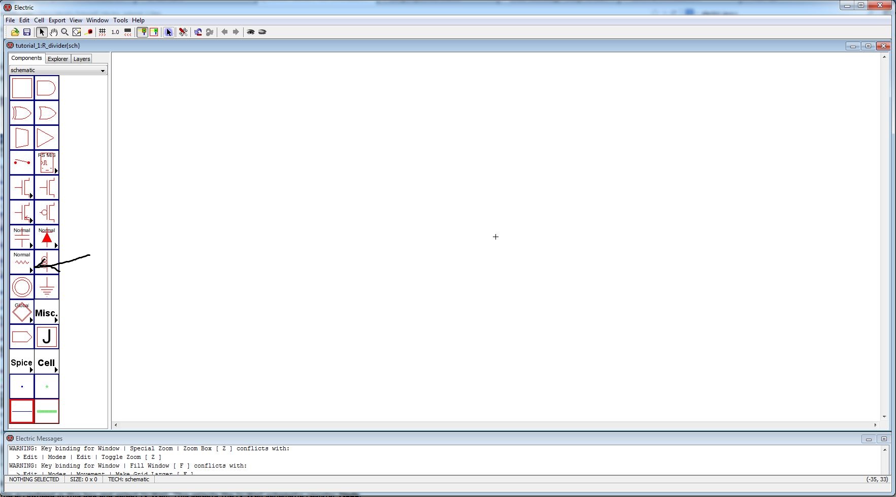
Your resistor should look like the following:
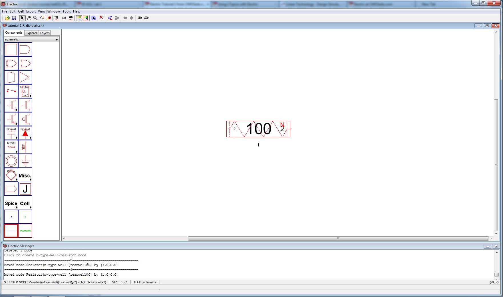
Step 7: Select the resistor, and go to Edit>Properties>Object Properties (or pressing Ctrl+I). Change the properties of the resistor to the following.
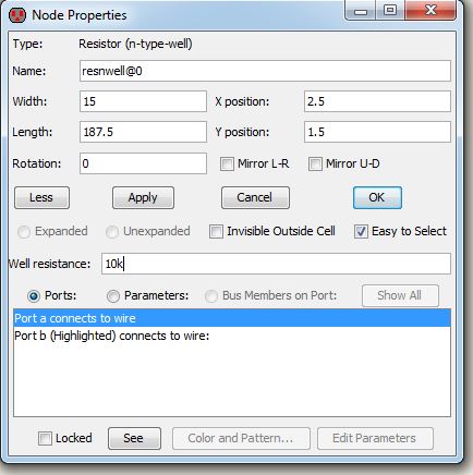
Step 8: Your resistor should look like the following.
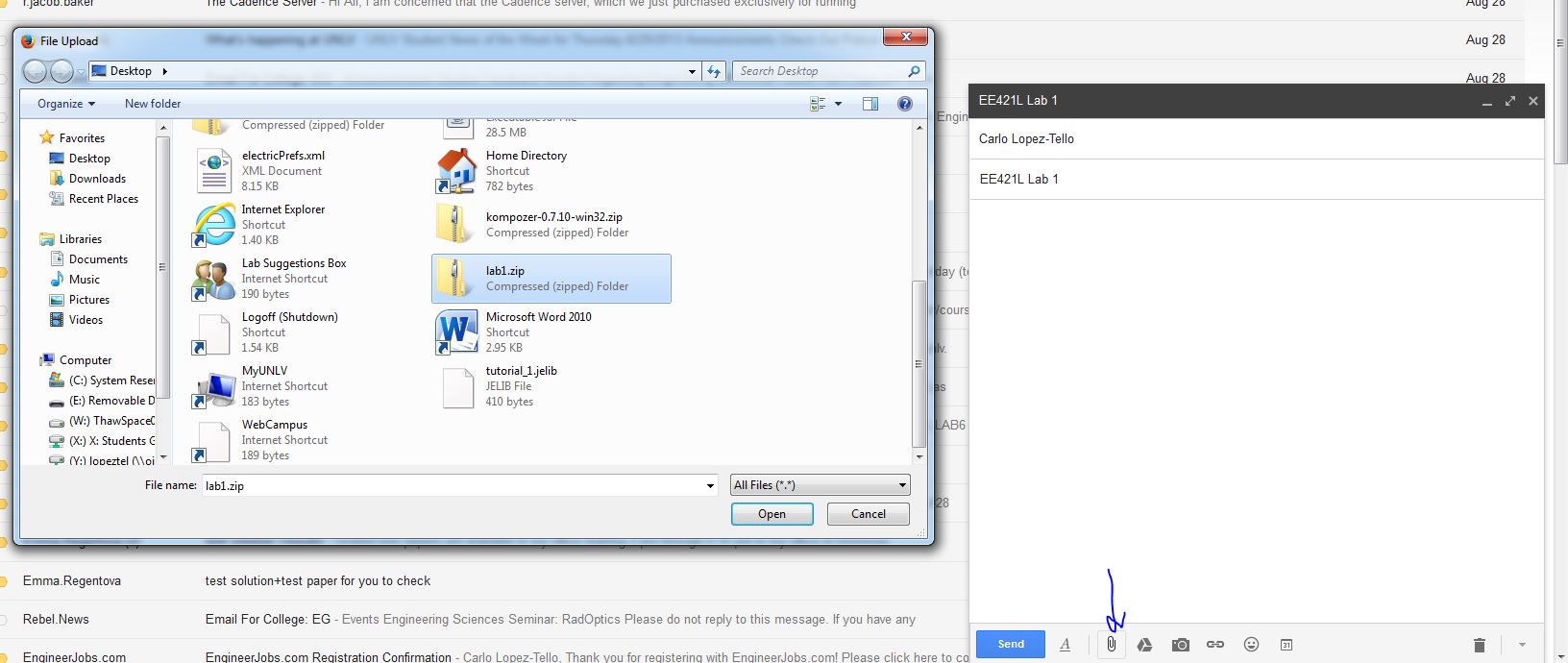
Step 9: Make sure to back up your work by uploading it somewhere online (email,dropbox,etc). Zip your working folder by right clicking it and going to Send to>Compressed(zipped) Folder.
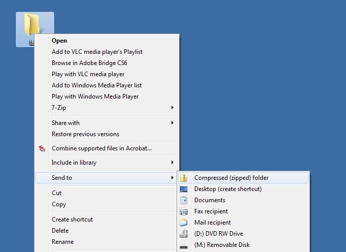
Email the folder to yourself.