Project - EE 421L

EE 421L Project 

Authored by Min Lan,

LANM2@UNLV.NEVADA.EDU

11/22/2013


Electric library:    ML_ee421L_f13_Project.jelib

IRSIM input vector:   ML_ee421L_f13_Project_8_bit_ALU.cmd


Project description

        In this project we will create an 8-bit ALU that performs 4 operations: bit-wise AND, bit-wise OR, addition, and subtraction.


ALU Specification:

        The ALU will take 2 data inputs of 8 bits each (A[7:0] and B[7:0]), and a 2-bit function selector F[1:0] that chooses operation to be performed. The ALU will have an 8-bit output Z[7:0].

images/alu_8bit_ic.png


Schematic:

        The ALU uses a 2-to-1 MUX to select between logical operations (AND & OR) and arithmetic operations (ADD & SUB); the selection signal is F[1]. If F[0] = 0 (logical operation), F[0] is then used to select between AND and OR operations. If F[0] = 1 (arithmetic operation), F[0] is used to select between Addition and Subtraction operations. For each type of operation, a 2-to-1 MUX is needed.


F[1:0]                Z[7:0]
-----                    -------
00                    A AND B
01                    A  OR  B
10                    A   +   B
11                    A    -   B


Bit-wise AND:

The AND operation will utilize the 8-bit AND2 device created in lab 7.

Bit-wise OR:

The OR operation will utilize the 8-bit OR2 device created in lab 7.

Addition:

The ADD operation will utilize the 8-bit Adder created in lab 7.

Subtraction

The SUB operation will be implemented with an 8-bit Adder, Z = A - B is obtain by adding A with (-B) where (-B) is the negation of B in 2's complement. (-B) can be obtained by bit-wise invertion and adding 1. This '1' will be tied to Cin of the Adder, effectively adding A and (-B).


images/alu_8bit_sch.png


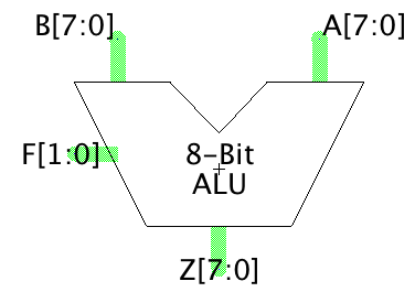
Simulate ALU Schematic with IRSIM

Input vector for IRSIM:   ML_ee421L_f13_Project_8_bit_ALU.cmd

       Let A = 010111012 = 9310 = 0x5D (hex)

             B = 010010112 = 7510 = 0x4B (hex)


       F[1:0] = 00 (AND):              Z = A AND B = 010010012 = 0x49 (hex)


       F[1:0] = 01 (OR):                 Z = A OR B = 010111112 = 0x5F (hex)

images/sim_alu_8bit_IRSIM_AND_OR.png

       F[1:0] = 10 (Addtition):         Z = A + B = 93 + 75 = 168 = 0xA8 (hex)


       F[1:0] = 11 (Subtraction):      Z = A - B = 93 - 75 = 18 = 0x12 (hex)

images/sim_alu_8bit_IRSIM_ADD_SUB.png


Layout

To lay out the 8-bit ALU, layouts for 2-to-1 multiplexer (single bit and 8-bit), 8-bit AND, 8-bit OR, and 8-bit inverter are needed in additional to elements completed in labs 1 through 7.

The layouts for these devices are straight forward with arrays.


ALU Top-level Layout


images/alu_8bit_lay_top.png

AND

OR

Inverter

MUX

MUX

MUX

8-Bit ADDER


Make sure layout passes DRC, LVS, and Well Check

images/alu_8bit_lay_checks.png


Simluate ALU Layout with IRSIM

Input vector for IRSIM:   ML_ee421L_f13_Project_8_bit_ALU.cmd


Layout simulation uses the same input vector file.


       Let A = 010111012 = 9310 = 0x5D (hex)

             B = 010010112 = 7510 = 0x4B (hex)


       F[1:0] = 00 (AND):              Z = A AND B = 010010012 = 0x49 (hex)


       F[1:0] = 01 (OR):                 Z = A OR B = 010111112 = 0x5F (hex)


       F[1:0] = 10 (Addtition):         Z = A + B = 93 + 75 = 168 = 0xA8 (hex)


       F[1:0] = 11 (Subtraction):      Z = A - B = 93 - 75 = 18 = 0x12 (hex)

images/sim_alu_8bit_lay_IRSIM_annotated.png

Result matches that of the ALU schematic and is correct.


Backup your files

images/email_backup.png


Return to EE 421 Labs