Lab 3 - EE 421L
Authored
by: Kendrick De La Pena
Date: September 13, 2013
Email: delape19@unlv.nevada.edu
Lab Description
Lab 2 will focus on the layout of the 10-bit DAC designed and simulated in Lab 2.
Lab Work
1)
First, we create a schematic for one section of the 10-bit
resistor-to-resistor DAC. The resistors are laid out in a serpetine
pattern to
match the layout.

2) For
each resistor, the size is 12 by 150. A resistor's total resistance is
calculated by multiplying the sheet resistance by length over width. For
this resistor, the sheet resistance is 800 Ohms, and the resistor must
equal 10k Ohms. Since design rules state that the minimum width must be
12, we chose 150 as the length.
Equation is as follows:
R sheet * (L/W) = R
To find the appropriate length:
L = (W * R) / R sheet
L = (12 * 10k) / 800 = 150
3) In
Electric, the length and width of a resistor are measured from end to
end on the resistor. Usually, the measurements do not include the pins
that connect to metal 1. To display the exact measurements, the
measuring tape pointer is used.
4)
Using the layout program, we set up a similar layout to the schematic.
The resistors are aligned vertically with pins for L, R, B, and ground.

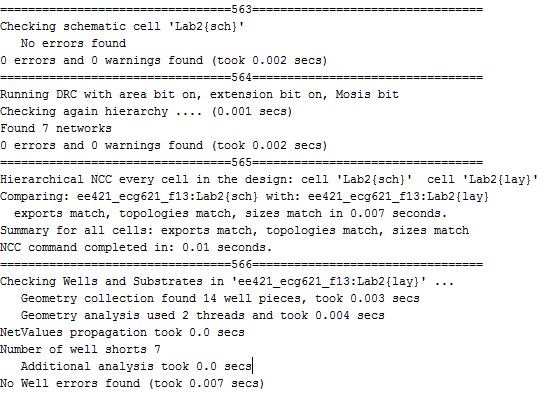
5)
The following shows the DRC check on the schematic first, then the
layout second. In addition, the NCC check is ran to make sure the
schematic
and the layout match, and an ERC check is ran to make wells are not
placed close together and connected. No errors show for all checks
Return to Kendrick's labs