
Lab Project - EE 421L
Most of the components of the ALU have been created in other labs, so now it will be a task of assembling the ALU. 2 8-bit 2 to 1 demuxs will be used to select either the output from A or B, A and B, or the output from the 8 bit full adder. The 8-bit full adder performs either addition by inputting A, B, and Cin=0, or subtraction by inputting A, B', and Cin=1. This setup is accomplished by inputting the F1 control signal into both the Cin for the full adder as well as using it for a control signal for the 8-bit demux (thus selecting B' for each input into the full adder). It is observed that this setup essentially takes the 2's complement of B (B is inverted and Cin=1 essentially adds 1). The schematic is constructed as shown below.

I needed to resolve an issue with the 8 bit 2 to 1 demuxs to get them working correctly. Namely, control signals of zero were not selecting the top input, which is logical. Upon resolving this issue, I proceeded to try a few different IRsim stimuli to ensure correct operation. First I let A = 50 (0x32) and B = 56 (0x38). I deliberately selected numbers that would result in a negative number at the output for the A-B operation. The IRsim confirmed the ALU's functionality for these inputs as shown below. The stimulus for this simulation is found in proj/proj_electric_files/ALU_sim_Aequals50_Bequals56.

This produces the correct result for A OR B (=0x3A), A AND B (=0x30), A+B(=0x6A), A-B(0xFA).

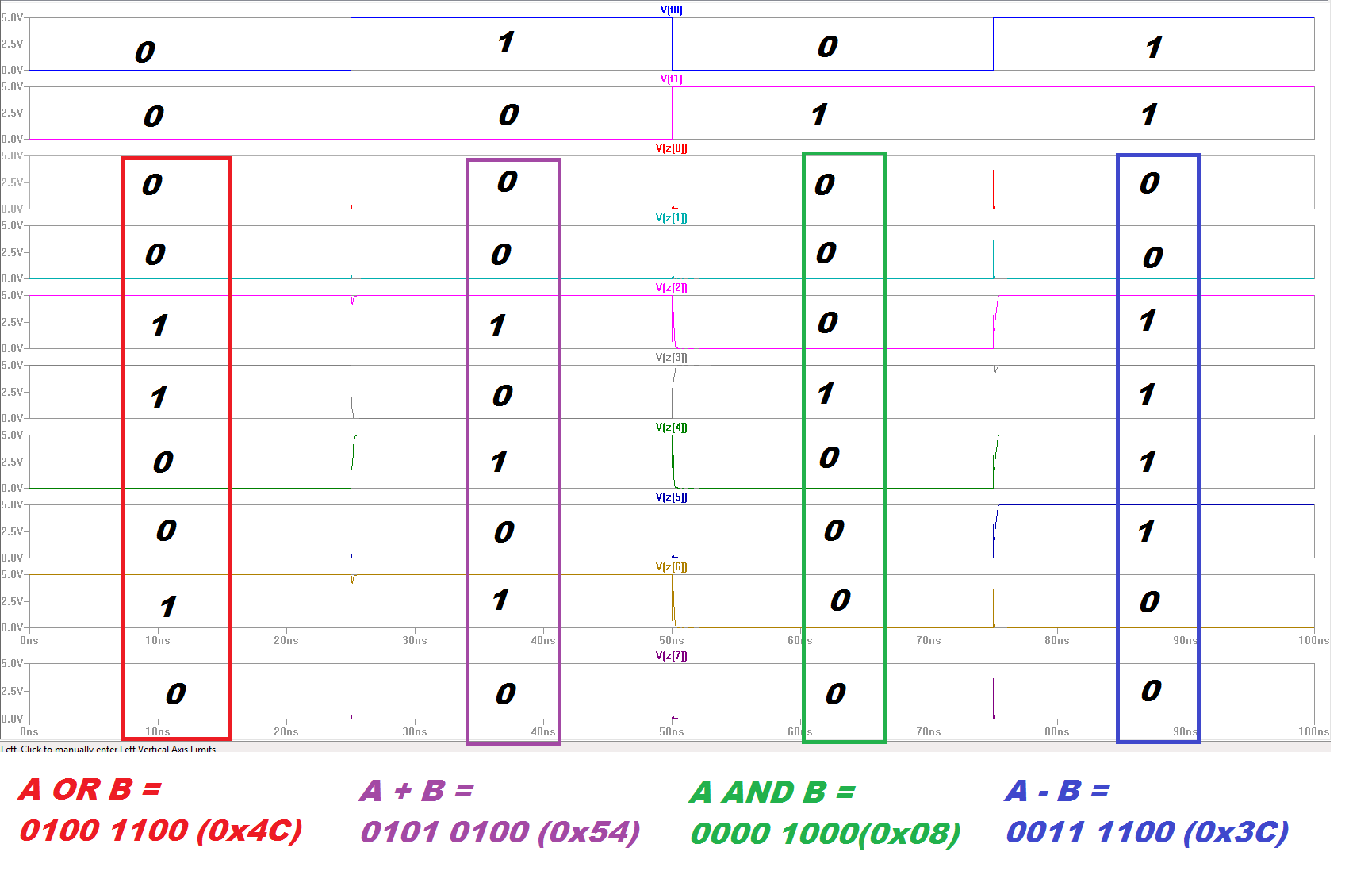
Again the outputs match hand calculations (A OR B = 0x4C, A AND B = 0x08, A + B = 0x54, A - B = 0x3C).
It is possible that IRsim is not catching some flaw that a Spice simulation would catch. Thus it would be diligent to test functionality in a spice simulation. Thus the operation is checked for a third time with spice. Shown below is the spice simulation circuit and simulation results. This simulation is found in the project jelib in a schematic named "alu_spicesim".


 Thus
Thus
This concludes my ALU design. As always I back up my work.

The Electric files for the project are found here and here.