Lab 5 - EE 421L 

Authored by Chad Johnson,

ctjohnso@unlv.nevada.edu

10/4/13


In this lab we will layout two inverters. One will utilize a 20/2 pmos and a 10/2 nmos, and the other will utilize a 100/2 pmos (set up as 5 20/2 pmos in parallel) and a 50/2 nmos (set up as 5 10/2 nmos in parallel). After we have created the inverters we will simulate their functionality with different capacitive loads with spice, IRsim, and ALS.


First I completed the tutorial which assisted me in constructing the 20/10 inverter. The 20/10 inverter layout, schematic, and icon are shown below.


Shown below is the layout, schematic, and icon for the 100/50 inverter.


Next the inverters are simulated. First the spice engine was used to simulate. a 100fF capacitive load was applied to the inputs of both inverters and the outputs were observed. The schematics and outputs for this simulation are shown below,


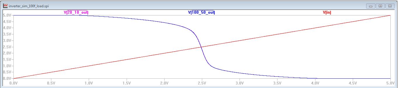
Simulation yielded the following results. Note that the outputs of the inverters are nearly idential


Next the capacitive load was increased to 1 pF. The schematic and spice simulation are shown below.


Again we note the similar response from the 20/10 inverter and the 100/50 inverter.


Lastly, we again adjust the load to 10pF and run the spice simulation again. Again we observe a very similar response from the two inverters. The schematic for the simulation as well as the results are shown below.


 Next I use the built in simulators IRsim and ALS.  First we simulate with ALS. We note that ALS is simulates only logic and doesn't consider transistor level non-idealities. Thus the ALS simulation does not consider the delay from the capacitive load.


We note that the ALS does not consider the capacitive load and the simulations are insensitive to changes in the capacitive load.


Shown below is the simulation circuit and results of the IRsim simulation. The IRsimulation includes the considerations and non-idealities of transistor level design. Thus it is capable  of demonstrating the delays associated with the circuit. Shown below is the circuits and simulations with the different capacitive loads.


It is clear that IRsim considers the higher capacitive load unlike ALS which ignores it. The 10pf load clearly takes longer to respond to the change in the input.


This concludes the lab work. I back up my work as shown below.


Lab5 jelib is found here.

Return to Chad Johnson's EE 421 Lab Reports