
Lab 3 - ECE 420
This lab will make use of the op-amp LM324 and a few altering components to analyze basic topologies, finite gain, and offset. To support the values that we recieve in the experiments they will be compared to LTspice simulations, and hand calculations.
_____________________________________________________________________________________________________________________________
Lab
Part 1
From the data sheet linked above we can see that at ambient temperature (25 degrees Celcius) the common mode voltage ranges 0 to Vcc-1.5.
Image 1: Input Common Mode Voltage From data sheet.
The open-loop gain of the op amp or Aol at 1kHz is roughly 60dB, or 1000. From the graphs given in the data sheet we can also see that the Aol does not change dramatically with temperature so it can be estimated to be 1000 at 1kHz.

Image 2: Large signal voltage gain graph from data sheet.
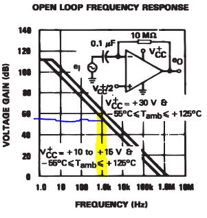

Image 3: Open loop frequency response graph and table from data sheet.
Looking at the data sheet linked above, when the at room temperature the offset should be 2mV.

Imgae 4: Input Offset Voltage from data sheet.
Worst Case scenario based on the data sheet the maximum input is 9mV, so I would expect the same for the offset.
------------------------------------------------------------------------------------------------
Part 2
For the second portion of the lab the students were given a circuit, seen below, and were tasked at recreating the circuit and measuring for VCM

Image 5: Circuit given to students to be recreated.
Following the creation of the circuit the following questions were asked.
What is the common-mode voltage, VCM? Does VCM change? Why or why not?
For this circuit the common mode voltage is 2.5V, because we have created a voltage divider with the 5V dc input feeding into two 10k resistors and two capacictors, which act like opens for dc.
The ideal closed loop gain for the op amp circuit is -RF/RI which would come out to -1. This means that th eoutput will have a closed loop gain of 1 and will have a 180 degree phase difference with the input.
The output swing is the 100mV ac signal that is input into the circuit which means that the ouput swings 100mV above and below the dc voltage 2.5V. This can be seen in both the Ltspice simulation and experimental values gathered below.

Image 6: Oscilliscope reading of the circuit given in Image 5.
For this circuit the maximum allowable input signal amplitude would be 2.5V as this would start to allow the line to reach Vcc and ground and will start to have cutoffs with both ends of the output. The cutoff can be seen in the images below.

Image 7:Oscilliscope reading showing cutoff voltage when above maximum allowable input signal amplitude.
If the gain is increased by 10 then the input has to be decreased by 10 in order to to stop the cutoff, thus 1/10 of 2.5V is 250mV.
The two capacitors in this circuit are there in order to decrease the effect of noise on the circuit. The values of these capacitors should have no impact on the circuit as they are acting with DC voltages not AC.
Since the circuit has the 20nA flowing out of its terminals if we increase the values of the resistor to be larger we are changing the voltage across the resistors. As mentioned before when the VCM starts to aproach Vcc or ground we start to see clipping, so as the resistor values get larger and larger we will get increasingly larger amounts of clipping.
The input offset current is the differnce of current of the terminals of the opamp and the input bias, from the data sheet the input offset current is 2nA while the input bias is 20nA.

Image :Input Offset and Bias current from data sheet
------------------------------------------------------------------------------------------------
Part 3
Explain how the following circuit can be used to measure the op-amp's offset voltage.
| Op Amp | Oscilliscope | Offset Calculation |
| LM 348 |  | |Vout-VCM|/20=|3.22-2.68|/20 =27mV |
| LM 339 |  | |Vout-VCM|/20=|3.22-2.68|/20 =10mV |
| TL081 |  | |Vout-VCM|/20=|1.62-2.40|/20 =39mV |
| UA741 |  | |Vout-VCM|/20=|2.62-2.56|/20 =3mV |