EE 420L Engineering Electronics II
Lab
Lab 5 - Op–amps III, the op–amp
integrator
email:
matacarl@unlv.nevada.edu
3/13/19
Pre-lab:
- Watch
the video op_amps_III,
review op_amps_III.pdf (associated
notes), and simulate the circuits in op_amps_III.zip.
- Read
the write-up seen below before coming to lab.
Lab description:
The goal of this lab is to calculate
the unity-gain frequency of the figure below, and to design and simulate a
triangle wave from a square wave input.
This lab will utilize the LM324
op-amp (LM324.pdf), and for questions and
experiments, VCC+ = +5V and VCC- = 0V
Experiment 1:
a)
Calculate the frequency
response of the following circuit. Ensure you show your clear hand
calculations.
o What can you neglect to simplify the calculation?
o Does the circuit work if you remove the 100k? Why or why not?
o Does the 100k have much of an effect on the frequency response?
b)
Verify your calculations
with experimental results.
c)
Show, at the unity-gain
frequency of the integrator, that the input and the output have the same peak
values.
o Is the phase shift between the input and the output what you
expect? Why or why not?

a)
Calculate the frequency response of the
following circuit. Ensure you show your clear hand calculations.

1) What can
you neglect to simplify the calculation?
First, we can neglect the DC circuit and the Common node voltage
and focus only on AC. Second, R2 (100K) is not affecting much
The frequency response, since we can divide by R2 and have the
same results.
2) Does the
circuit work if you remove the 100k? Why or why
not?

|
Circuit
without 100k resistor |
||
|
frequency |
LTspice results |
Experimental results |
|
10Hz |
|
|
|
159Hz |
|
|
|
1kHz |
|
|
|
10kHz |
|
|
|
Over 800kHz |
The output rails |
|


|
Circuit
with 100k resistor |
||
|
frequency |
LTspice results |
Experimental results |
|
10Hz |
|
|
|
159Hz |
|
|
|
1kHz |
|
|
|
10kHz |
|
|
|
Over 600KHz |
The output rails |
|


Note: The results shown above for the same
circuit with 100k and without, demonstrate that the 100K resistor does not
affect much the frequency response
3) Does the
100k have much of an effect on the frequency response?
The 100k resistor does not have much effect on the frequency
response because as shown in the hand calculations section
the top
and bottom of the magnitude is being multiplied by R2, which causes to have the
same ratio as if it wasn’t there.
B) Verify
your calculations with experimental results
Show, at the unity-gain
frequency of the integrator, that the input and the output have the same peak
values.
Is the phase shift between
the input and the output what you expect? Why or why not?
![]()


Experiment 2:
a)
Next, design,
simulate, and build a square-wave to triangle wave generation circuit.
b)
Assume the
input/output frequency is 10 kHz and the output ramp must swing from 1 to 4 V
centered around 2.5 V.
c) Show all
calculations and discuss the trade-offs (capacitor and resistor values, input
peak, min, and average, etc.)
a)
Next, design,
simulate, and build a square-wave to triangle wave generation circuit

b)
Assume the
input/output frequency is 10 kHz and the output ramp must swing from 1 to 4 V
centered around 2.5 V.
LTspice Simulations

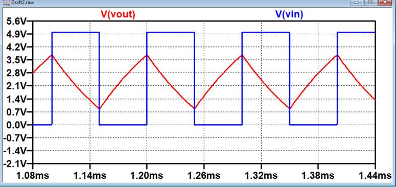
Experimental Results


c) Show all
calculations and discuss the trade-offs (capacitor and resistor values, input
peak, min, and average, etc.)
The
calculations for this circuit are shown above in part a).
Trades-offs
For experiment 1, the trade-ff is the values
of the resistors in relation to the capacitor to crate the unity gain frequency.
By increasing the
unity frequency gain, the value of R1 decreases,
which also increases the total gain of the output, if R2 is constant. Thus,
this increase in frequency
increases the input offset voltage,
which increases the offset of the output.

For experiment 2, the trade-ff is very
similar as for experiment 1. We want R2 and R1 to have a small gain because we
don’t want the input
offset voltage to affect the swing of
the output. But if R1 is increased in value, then the capacitor value will have
to be decreased in order to
maintain the ramp that is desired.
![]()
Return to student lab reports
Return
to labs