EE 420L Engineering Electronics II Lab
Lab 4- Op–amps II, gain-bandwidth product and slewing
email: matacarl@unlv.nevada.edu
2/27/19
Pre-lab:
- Watch
the video op_amps_II,
review op_amps_II.pdf (associated
notes), and simulate the circuits in op_amps_II.zip.
- Read
the write-up seen below before coming to lab.
Lab description:
The goal of this lab
is to test for different gains using inverting and non-inverting topologies and
experimentally find bandwidths and slew rate.
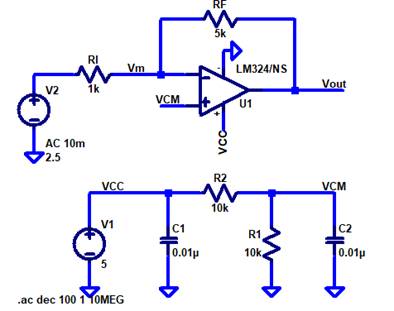
Experiment 1:
Estimate, using the datasheet, the bandwidths for non-inverting
op-amp topologies having gains of 1, 5, and 10.


The plot and information above show the open
loop gain and the Gain Bandwidth Product. This applies to voltages of VCC =30V,
and 10V to 15V. We are using VCC = 5V and VCC- = 0V. so it seems that. For the hand calculations we are using 1.3MHz
as GBW product to make estimates, and then show the results experimentally.
|
NON-Inverting topology |
||
|
LtSpice Simulations |
Experiments Results |
Hand Calculations GBW = 1.3MHz |
|
Gain =1 |
Gain=1 |
|
|
|
Input
(yellow) = 100mVpp (100mVpp)*(1) = 100mVpp Output
(blue) ≃ 70mVpp Comments:
The output seems to be lagging or having a phase shift. This is due to the
Slew Rate (SR), which is 400mV/𝞵s. The
frequency to maintain the change in voltage is about 65KHz |
GBW = 1.3MHz
|
|
Gain =5 |
|
|
|
|
Input
(yellow) = 20mVpp (input)*(gain)
= output voltage (20mVpp)*(5) = 100mVpp 3dB Output
(blue) ≃ 70mVpp Comments:
The lagging again is due to the Slew Rate (SR), which is 400mV/𝞵s. The
frequency to maintain the change in voltage is about 65KHz. The frequency
difference from the hand calculations and experiments results seems to be
related to the VCC voltage we are using. The smaller the VCC the lower the
Bandwidths seem to be. The open-loop frequency response plot shown in the
beginning with a 1.3MHz GBW seems to be calculated with VCC of 30V, however
we are using 5V for VCC. |
|
|
Gain = 10 |
Gain = 10 |
|
|
|
Input
(yellow) = 20mVpp (input)*(gain)
= output voltage (20mVpp)*(10) = 200mVpp 3dB Output
(blue) ≃ 144mVpp Comments: The frequency difference from the hand calculations and experiments results seems to be related to the VCC voltage we are using. The smaller the VCC the lower the Bandwidths seem to be. The open-loop frequency response plot shown in the beginning with a 1.3MHz GBW seems to be calculated with VCC of 30V, however we are using 5V for VCC. |
|


Experiment 2:
Estimate, using the datasheet, the bandwidths for inverting op-amp
topologies having gains of -1, -5, and -10.
|
Inverting topology |
||
|
LtSpice Simulations |
Experiments Results |
Hand Calculations GBW = 1.3MHz |
|
Gain =1 |
Gain=1 |
|
|
|
Input (yellow)
= 100mVpp (input)*(gain)
= output voltage (100mVpp)*(-1) = -100mVpp 3dB Output
(blue) ≃ -70mVpp Comment:
The 3dB was found at a frequency of about 5.7MHz. Not sure how this happen,
but perhaps we did not account for other factors. |
|
|
Gain =5 |
Gain =5 |
|
|
|
Input
(yellow) = 20mVpp (input)*(gain)
= output voltage (20mVpp)*(-5) = -100mVpp 3dB Output
(blue) ≃ -70mVpp Comment: The 3dB output voltage was found by using a frequency of about 225kHz, but the oscilloscope was not able to read this frequency. |
|
|
Gain = 10 |
Gain = 10 |
|
|
|
Input
(yellow) = 20mVpp (input)*(gain)
= output voltage (20mVpp)*(-10) = -200mVpp Output
(blue) ≃ -144mVpp Comment: The 3dB output voltage was found by using a frequency of about 108kHz, but the oscilloscope was not able to read this frequency. |
|


Experiment 3:
Design two circuits for measuring the slew-rate
of the LM324. One circuit should use a pulse input while the other should use a
sinewave input

The snapshot above is from the datasheet which
shows the Slew Rate (SR) to 400mV/𝞵s
The next set of calculations were used to find
the slew rate frequency.


![]()
|
Sinewave |
Squarewave |
|
1Vpp, 10kHz, No Slew Rate Shown |
1Vpp, 30kHz, Some Slew Rate Shown |
|
|
|
|
1Vpp, 170kHz, Slew Rate shown |
1Vpp, 170kHz, Slew Rate shown |
|
Because the slew frequency is about 63.7kHz for
1V, the output in picture above looks like a triangular wave because the
frequency being used is 170kHz, and the op-amp is not able to keep up with
the speed. |
The image above shows, again, a triangular wave because
the frequency is much higher than the slew frequency calculated above of
about 63.7kHz. Thus, the op-amp is not able to keep up with the speed. SR = |


Return to student lab
reports
Return
to labs