One
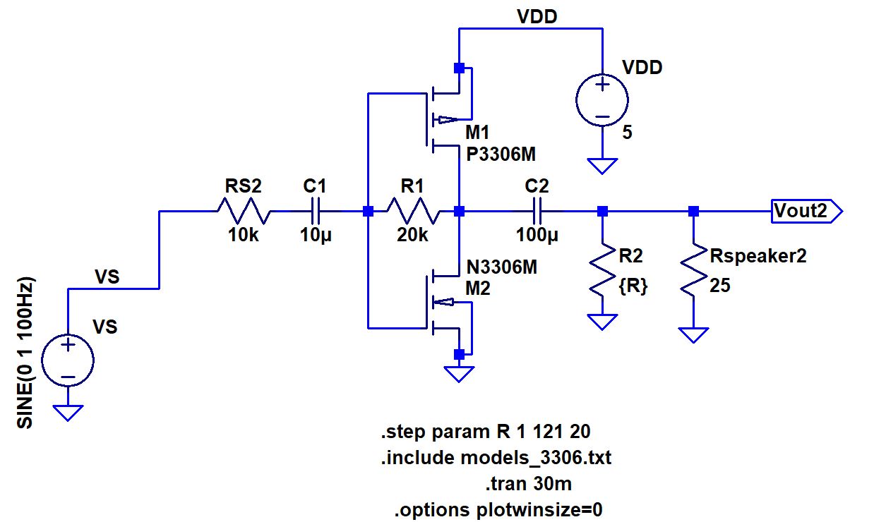
of the lower power consumption, but reasonable output is 20 Ohms.
However we used 25 Ohms to match the speaker and because it was
available in the lab
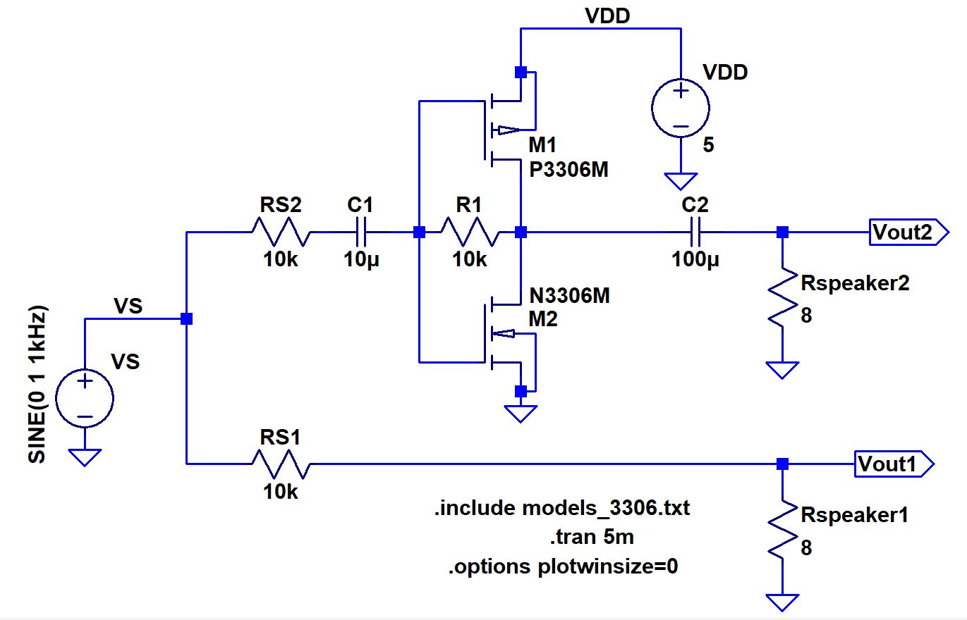
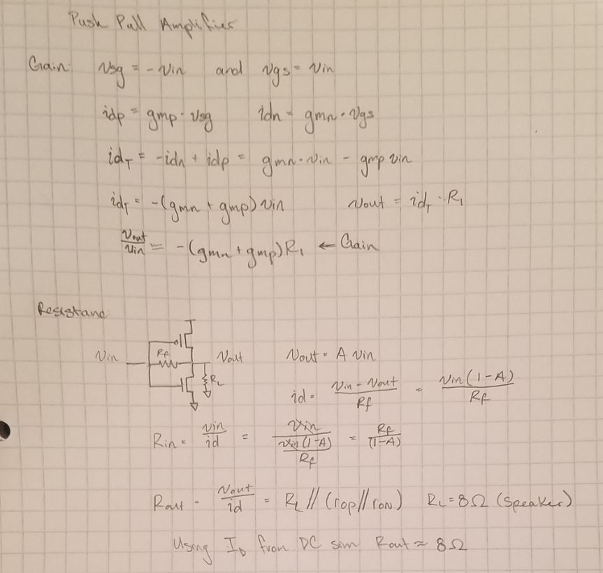
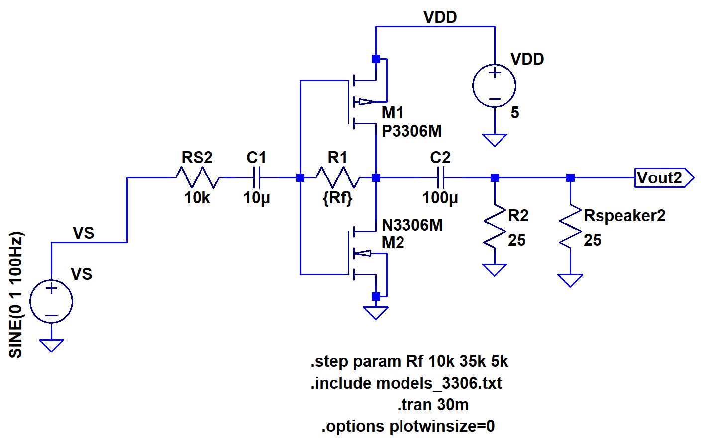
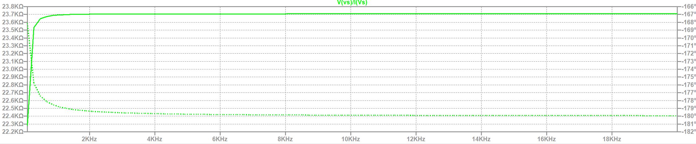
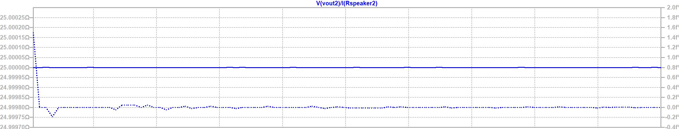
Now with 20KOhms for R1 and 25Ohms for
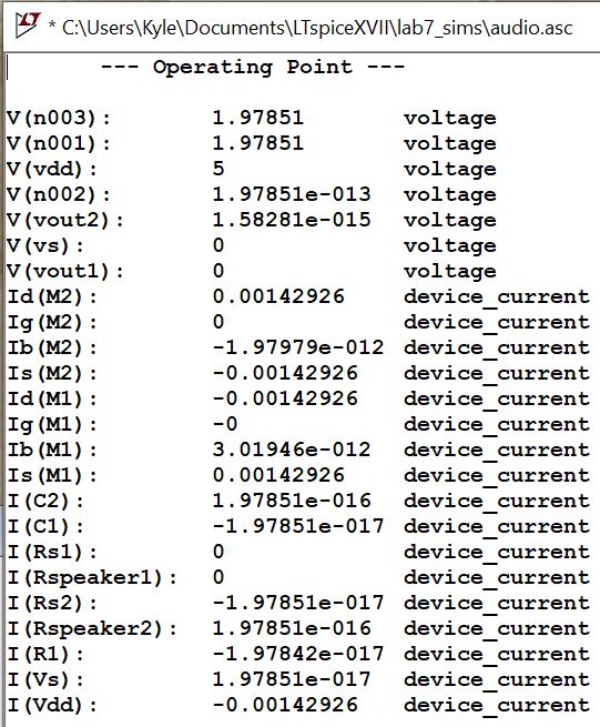
R2 lets look at the input and output resistance respectively. Sims show
~23KOhm for input and 25Ohm for output.
Building Circuit
Response
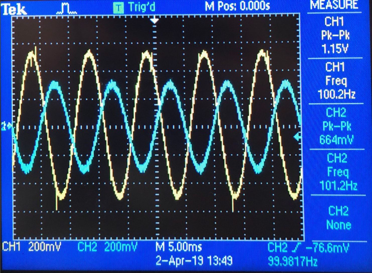
100Hz
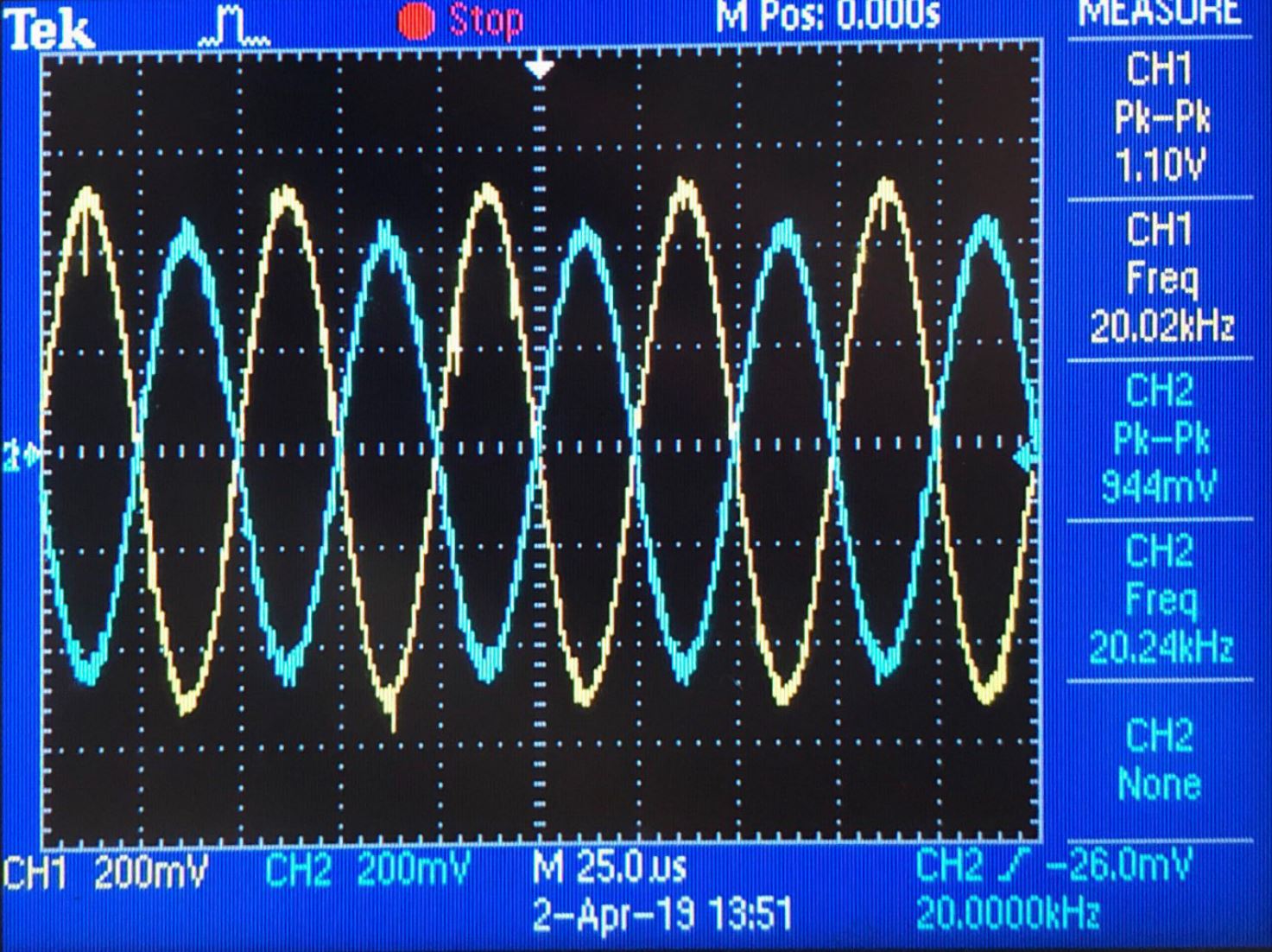
20KHz
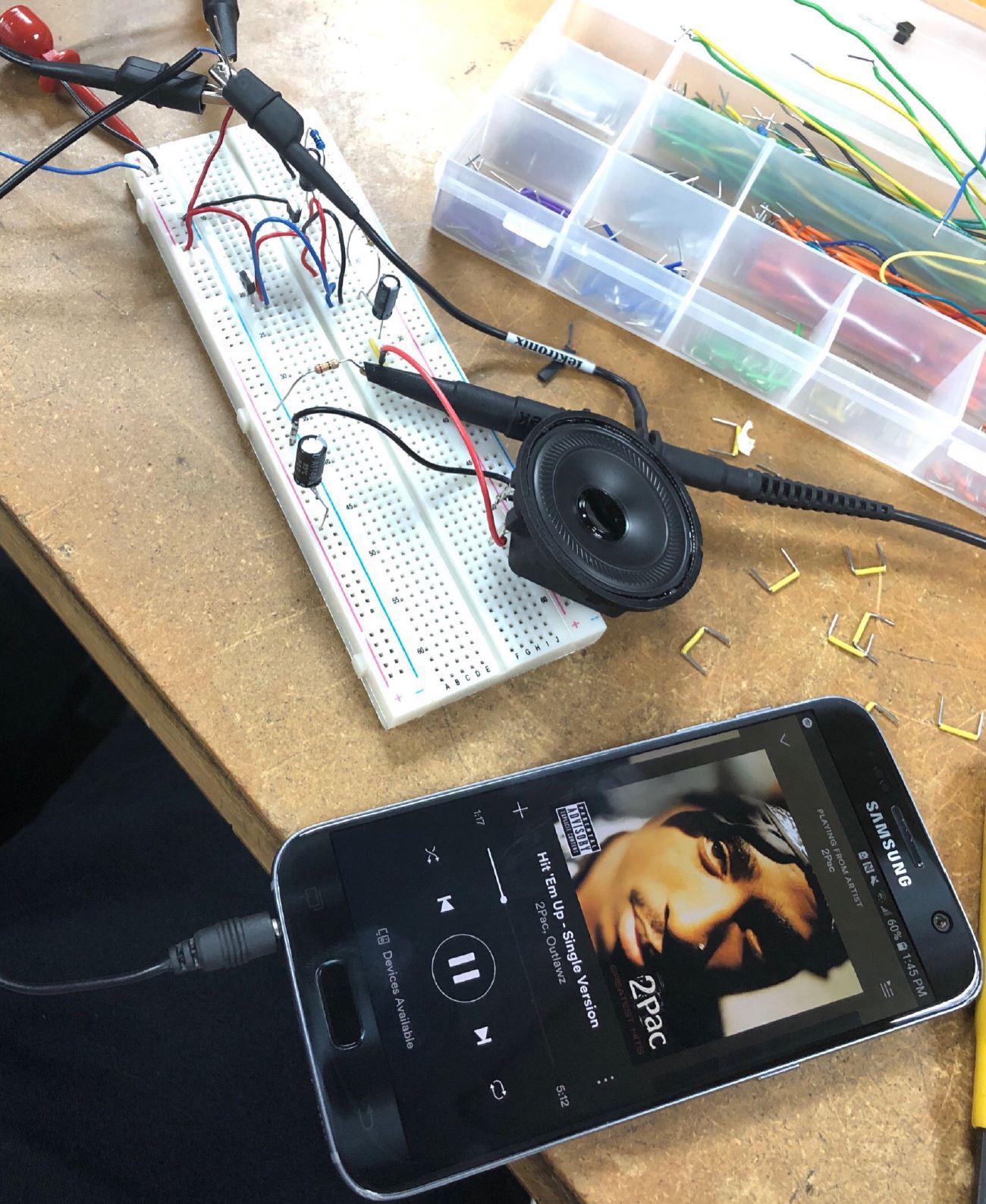
Circuit Test with MP3
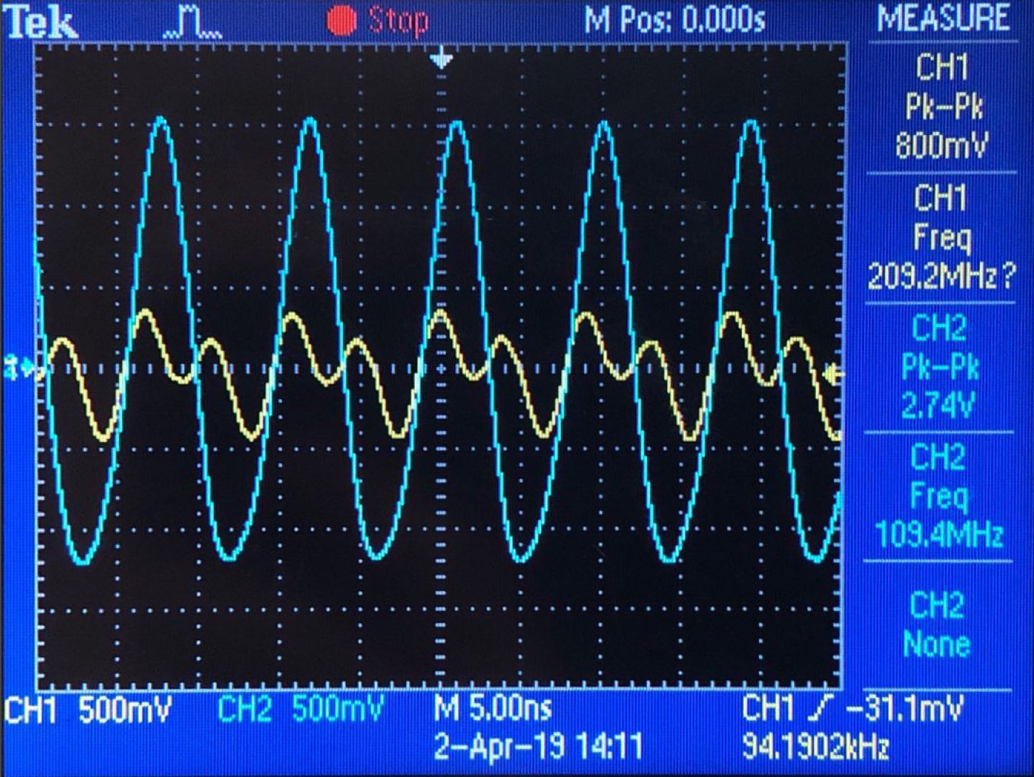
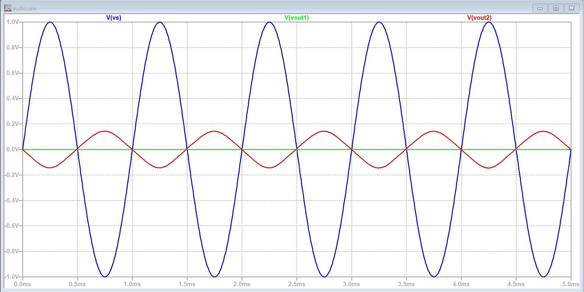
My output signal for 100Hz is 664mV and 944mV at 20KHz. My simulations for 100Hz showed approx.
350mV for a 1V input. While I did achieve a negative gain for a push
pull amplifier correctly, for some reason when using the MP3 signal as
input my gain was abnormally high.
I am assuming we shorted some
connections when connecting out AUX cables. I was able to hear Hit'Em
Up by 2PAC clearly through the speaker, but the signal generator had
significantly more volume.