Lab 2 - ECE 420L
Authored
by Kyle Butler, butlerk2@unlv.nevada.edu
2/8/2019
Pre-lab work:
- Prior to the lab watch the scope_probe video and review the associated notes for the quiz.
- Vary
the parameters in the simulations found in the provided simulations to
understand the operations of the compensated 10:1 scope probe.
- From lab 1 ensure that you understand the operations and analysis of simple RC circuits
- Ensure that you can read and create Bode plots for corresponding signals in the time-domain at a particular frequency.
- Read the entire lab write-up before attending lab.
Lab work:
- Show
scope waveforms of a 10:1 probe undercompensated, overcompensated, and
compensated correctly.
- Comment
on where the type of scope probe (i.e., 1:1, 10:1, 100:1, etc.) is set
on your scope (some scopes detect the type of probe used automatically).
- Draft
the schematic of a 10:1 scope probe showing: the 9 MEG resistor, 1 MEG
scope input resistance, capacitance of the cable, scope input
capacitance, and capacitance in the probe tip.
- Using
circuit analysis, and reasonable/correct values for the capacitances,
show using circuit analysis and alegbra (no approximations), that the
voltage on the input of the scope is 0.1 the voltage on
the probe tip.
- Devise
an experiment, using a scope, pulse generator, and a resistor, to
measure the capacitance of a length of cable. Compare your measurement
results to the value you obtain with a capacitance meter. Make sure you
show your hand calculations.
- Build
a voltage divider using two 100k resistors. Apply a 0 to 1 V pulse at 1
MHz to
the divider's input. Measure, and show in your report, the output of
the divider when probing with a cable (having a length greater than or
equal to 3 ft) and then a compensated
scope probe. Discuss and explain the differences.
- Finally,
briefly discuss how you would implement a test point on a printed
circuit board so that a known length of cable could be connected
directly to the board and not load the circuitry on the board.
Scope waveforms
In
order to change the wave form from undercompensated/overcompensated to
compensated simply rotate the screw inside of the connection terminal
on the scope probe.
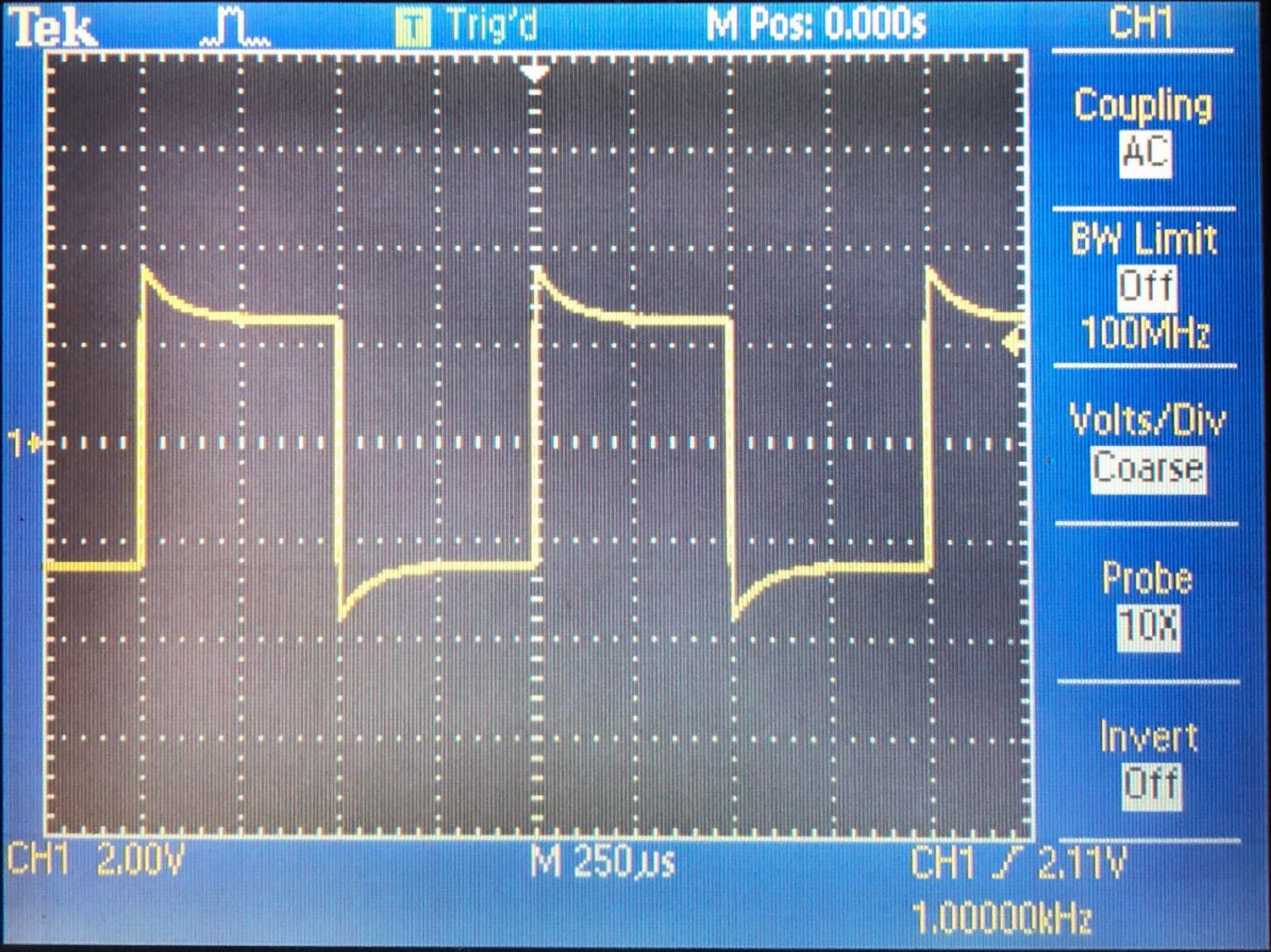
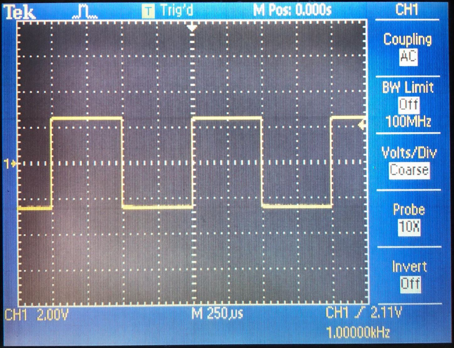
Below
are the wave forms for undercompensatred, overcompensated, and
compensated respectivly. Measurements are best when using a compensated
probe.
Scope type settings
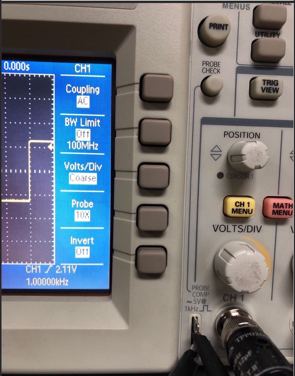
It
is key to select the probe multiplier on the oscilloscope to match the
probes scale (1x, 10x, or 100x). For this lab we chose to use 10x probe.
To
do this begin by selecting the proper channel menu, we used the channel
1 menu button. This will bring up a small side window on the
oscilloscopes monitor.
Using the fourth button from the top will
change the probes multiplier, from the image below you can see we
selected a 10x probe setting.
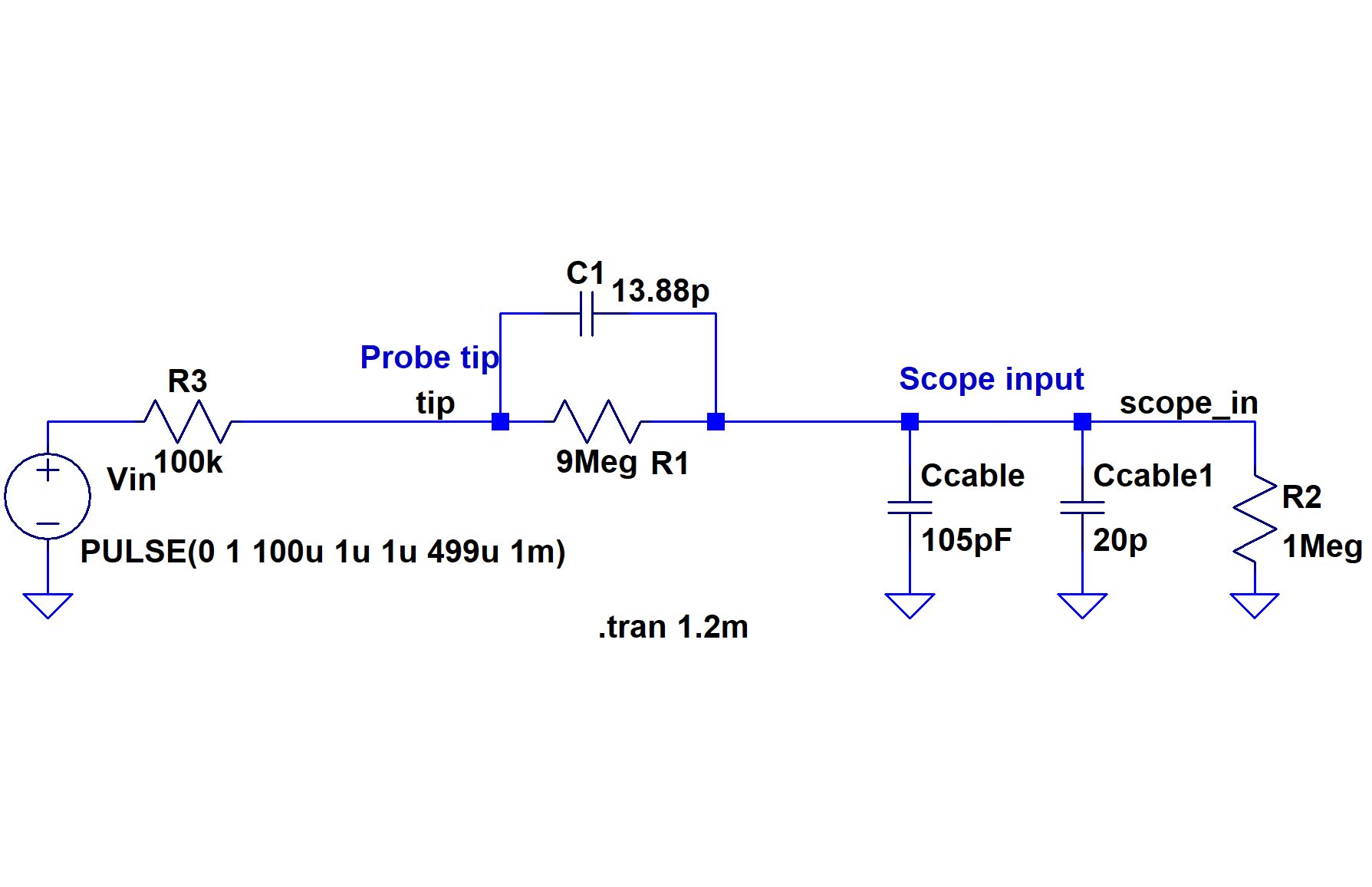
Draft schematic of 10:1 scope probe
For this section Dr. Baker has provided schematic of a 10:1 scope probe. We can see the 10:1 scale by measuring the scope_in voltage and seeing if the tip voltage is greater by a factor of 10.
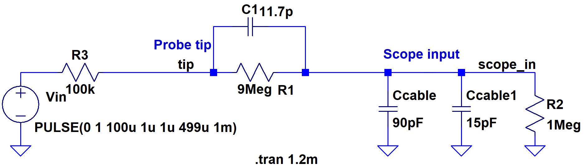
The
above schematic contain vaules given by Dr. Baker from the prelab. To
properly simulate the tools used in lab we will need to change some
values. Firstly we will change the scope_in capacitance to the
input impedance of the oscilloscope used in lab. We are using the TSD2xx oscilloscopes in the tbe350 lab.

For
the sake of simplicity we will use 20pF for Ccable1 in the schematic.
Next we will need to find the value of the Ccable capacitor, we used
the multimeter to find the capacitance of a similarly lengthed cable.
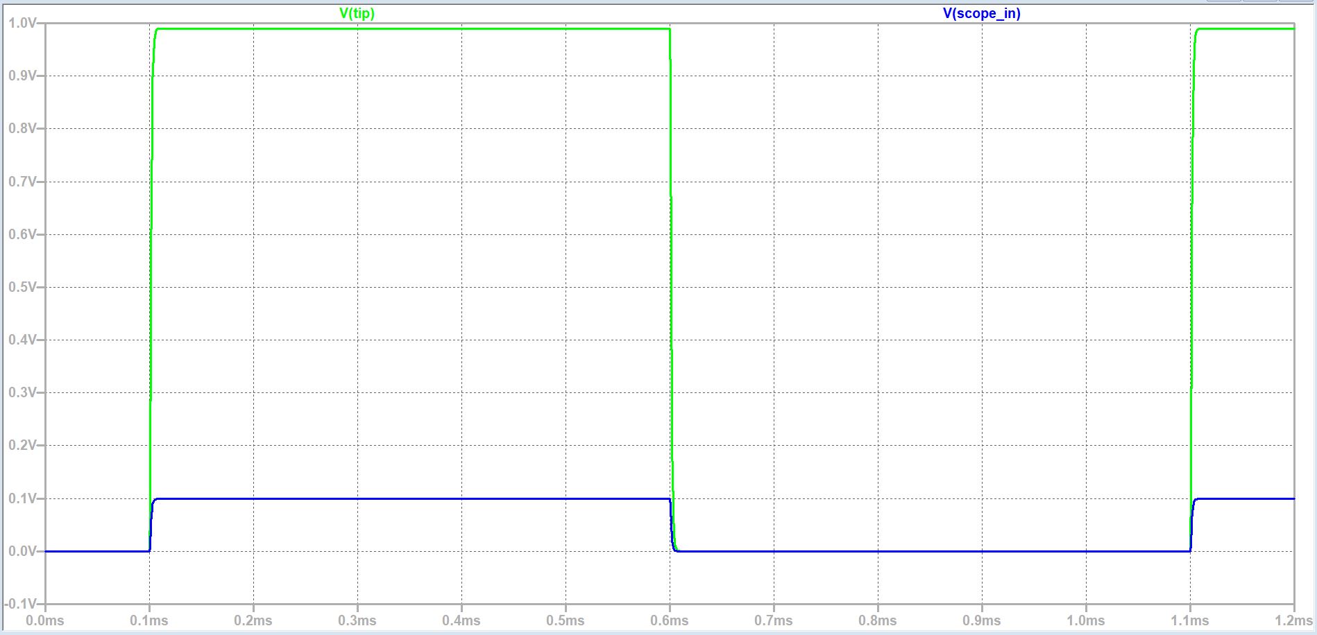
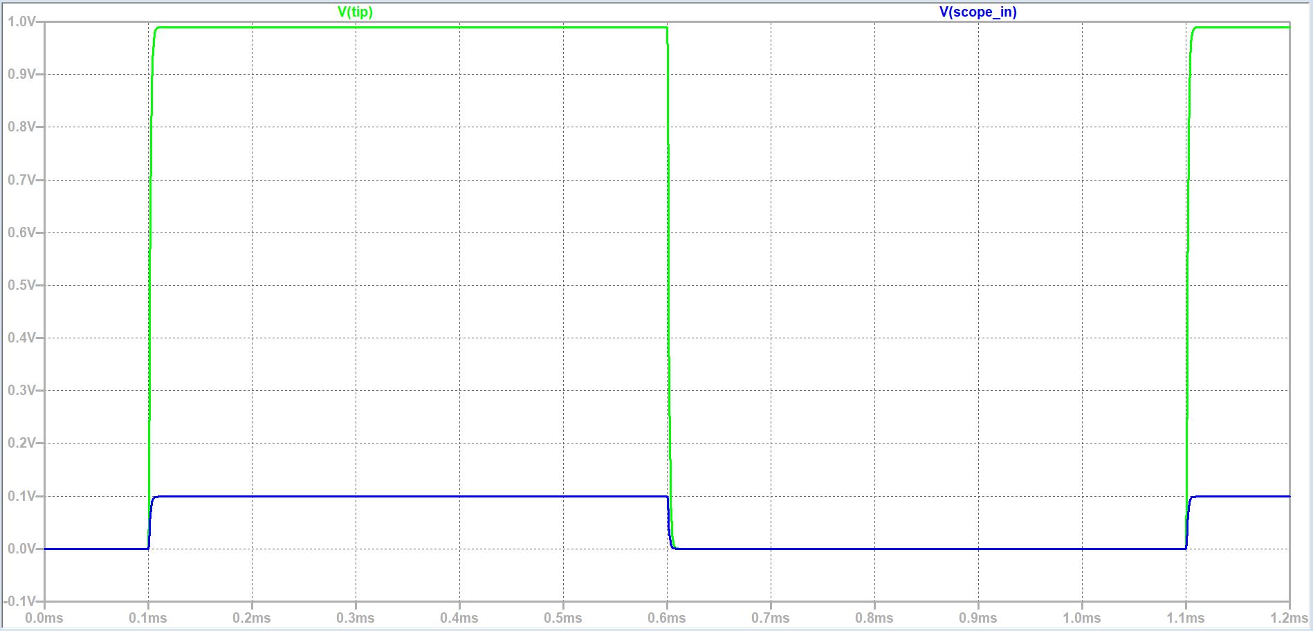
Lets re-run the simulation with the new values. As you can see below the waveforms now look undercompensated.
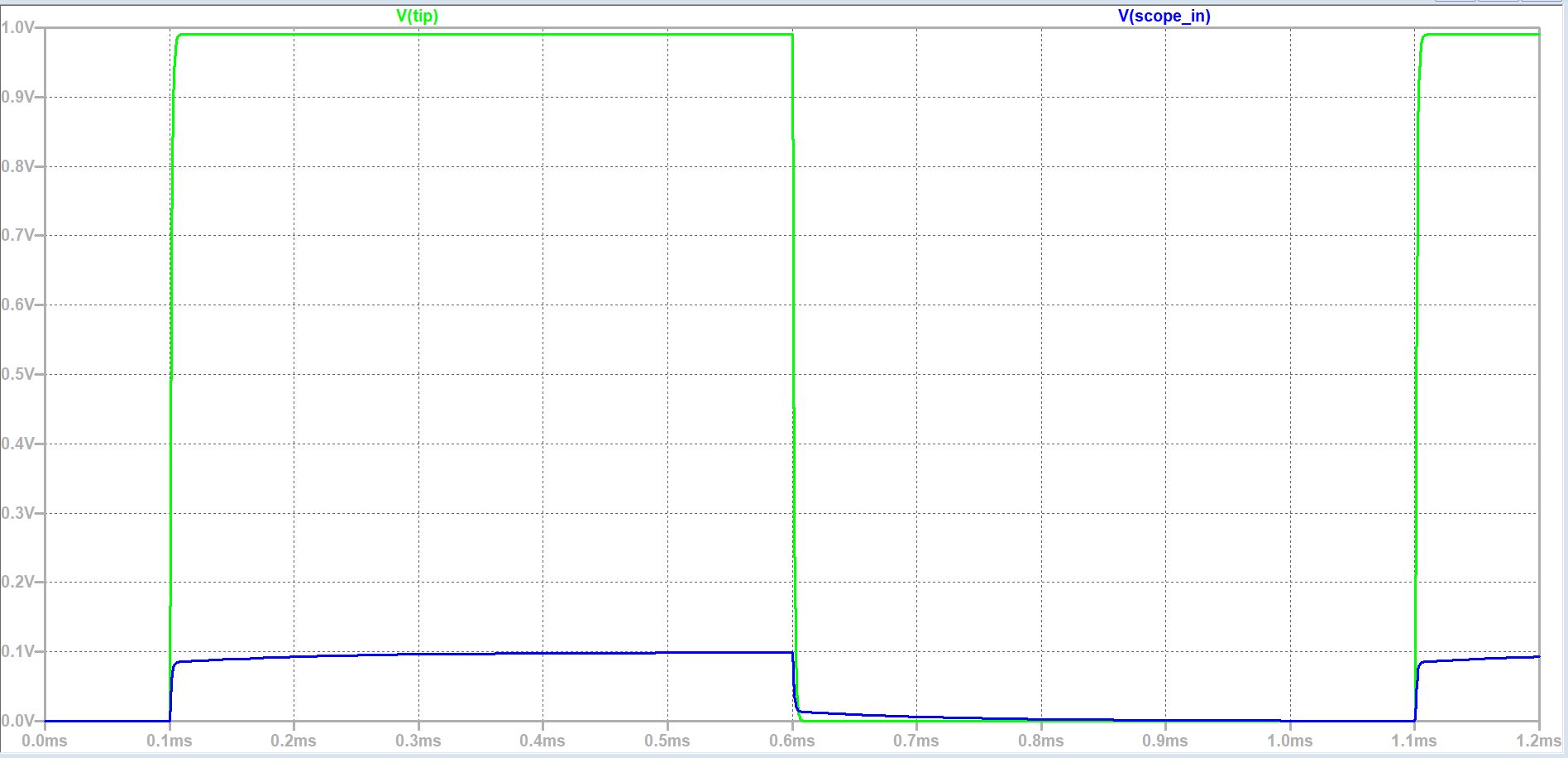
We
always compensate our scope tip before taking measurements. So we need
to replace C1 in the simulation with a new value to represent a
compensated probe, similar to experimental measurements.
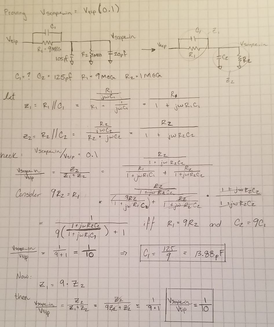
To do
this we will use circuit analysis, additionally we will prove that the
voltage on the input of the scope is 0.1 the voltage on the probe tip.
Circuit analysis
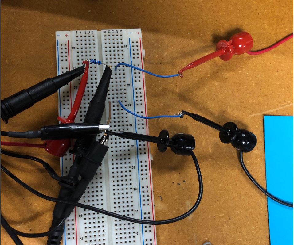
Devise an experiment
Our
goal is to measure the capacitance of the cable on the scope probe. To
test this we will make a RC circuit using a 100k resistor and the cable
for capacitance. Using this RC circuit we will measure the time
constant and solve for C.
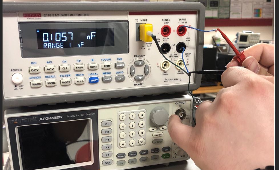
Below is out circuit laid out on a
breadboard, the blue wires are connected to our cable used to represent
capacitance. Next to this image is our measured RC response.
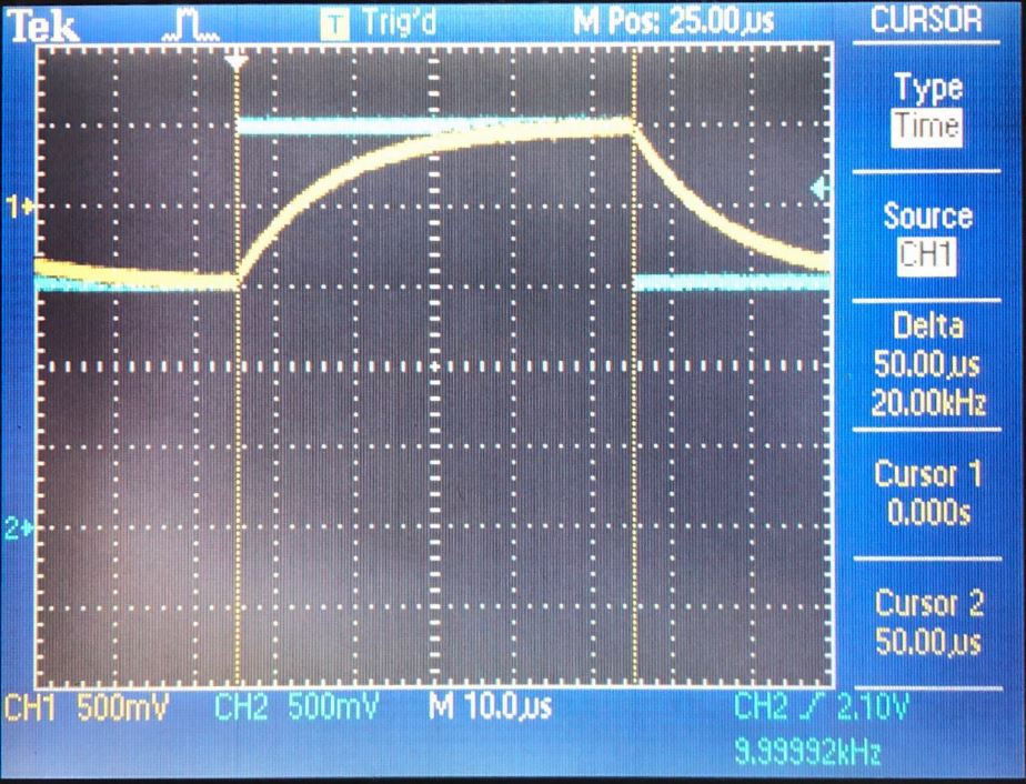
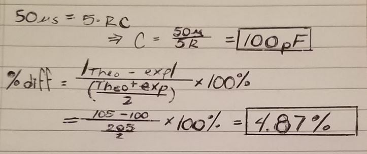
From the RC response we can see a steady state vaule of 50uS, below are hand calculations to solve for C1.
Voltage divider with probe and cable
First we will measure the voltage divider using the compensated probe followed by measuring with the cable.
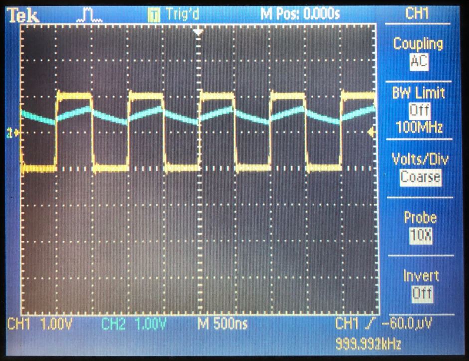
The
image on the left is measuring the voltage divider with a compensated
probe, the probe has a smaller capacitance when compared to the cable.
We know this because we are able to see a charge and discharge in a
10kHz pulse.
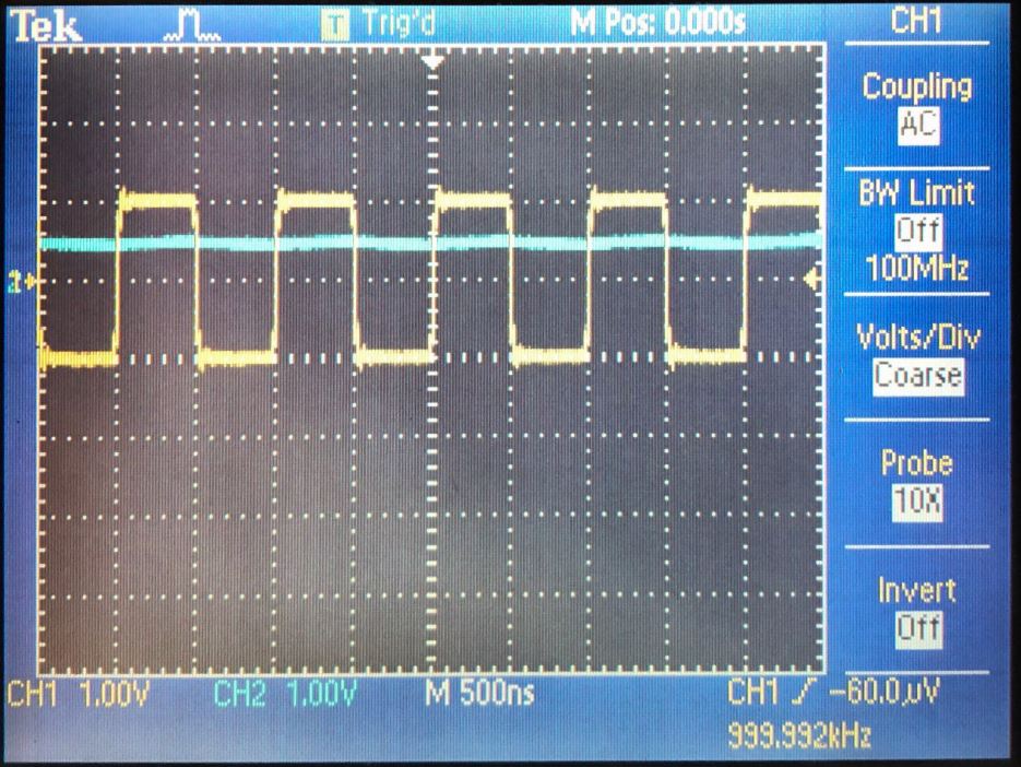
If the capacitance was larger, like the image of the
cable measurement on the right, the charge and discharge rate would be
to slow to see during a pulse.
Test point
When
designing a circuit for a PCB layout it is important to consider the
permanence of the components. In order to not load our circuity on the
board when connecting a cable we need some way to vary the capacitance
with the length of the connected cable.
This can be done with a
variating capacitor. Similar to the screw on a scope probe, we will
change the onboard capacitance in order to compensate for a known
length of cable.
Return to EE 420L Labs