|
Lab 4: Op-amps II, gain bandwidth product and slewing- EE 420L
Author: Mario Verduzco Email: Verdum1@unlv.nevada.edu Date: 02/22/17
|
|
Pre-lab: · Watch the video op_amps_II, review op_amps_II.pdf (associated notes), and simulate the circuits in op_amps_II.zip. · Read the write-up seen below before coming to lab. |
|
Lab description: The objective of this lab is to measure the bandwidths for the LM324 Op-amp using the non-inverting and inverting topologies having various gains. Also, we will measure the slew rate of the Op-amp when a sine wave and a pulse wave is applied as an input. |
|
Experimental Results: Experiment #1: Non inverting Op-amp topologies with a gain of 1, 5, and 10 |
|
Experiment #2: Inverting Op-amp topologies with gains of –1, -5, and –10 |
|
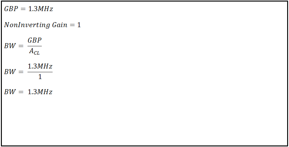
Using the Op-amp datasheet we can find the gain-bandwidth product of the device and be able to estimate the bandwidths of the different gains. |

|
Fig 1.1 – LM324 Gain Bandwidth Product |
|
|


|
|


|
1) Non inverting topology Gain = 1 |
|
Table 1.1 – Theoretical Bandwidths at a certain Gain |


|
Fig 1.2 – Non inverting topology Gain = 1
|
|
Fig 1.3 – Output (purple waveform) 3dB frequency
|
|
2) Non inverting topology Gain = 5 |


|
Fig 1.4 – Non inverting topology Gain = 5
|
|
Fig 1.5 – Output (purple waveform) 3dB frequency
|
|
3) Non inverting topology Gain = 10 |

|
Fig 1.6 – Non inverting topology Gain = 10
|

|
Fig 1.7 – Output (purple waveform) 3dB frequency
|
|
Using the Op-amp datasheet we can find the gain-bandwidth product of the device and be able to estimate the bandwidths of the different gains. |

|
Fig 1.8 – LM324 Gain Bandwidth Product |

|
|


|
|

|
|
|
Table 1.3 – Theoretical Bandwidths at a certain Gain |
|
1) Inverting topology Gain = -1 |


|
Table 1.2 – Theoretical and experimental Bandwidths at a certain gain |

|
Fig 1.9 – Inverting topology Gain = -1
|
|
Fig 1.10 – Output (purple waveform) 3dB frequency
|
|
2) Inverting topology Gain = -5 |


|
Fig 1.11 – Inverting topology Gain = -5
|
|
Fig 1.12– Output (purple waveform) 3dB frequency
|
|
2) Inverting topology Gain = -5 |


|
Fig 1.13 – Inverting topology Gain = -10
|
|
Fig 1.14– Output (purple waveform) 3dB frequency
|
|
Table 1.2 – Theoretical and experimental Bandwidths at a certain gain |
|
Experiment #3: Design of a circuit to measure slew rate |

|
Fig 1.15 – 2v sine wave with unity gain
|
|
Fig 1.16– Output (purple waveform) slewing at 40KHz
|
|
Fig 1.17 – 2v square wave with unity gain
|
|
Fig 1.16– Output (purple waveform) slewing at 10KHz
|
|
The experimental results differ from the theoretical results that were calculated using the data sheet. On reason for this discrepancy could be because the Op-amp GBP was measured using a Vcc = 30v, Vin = 10mV, Rl = 2k and CL = 100pF. So for this experiment the initial parameters were different. However the bandwidth did decrease dramatically as the gain increased. |
|
The results for the Inverting Op-amp were similar to the results of the Noninverting topology in that the experimental results differ from the theoretical results that were calculated using the data sheet. On reason for this discrepancy could be because the Op-amp GBP was measured using a Vcc = 30v, Vin = 10mV, Rl = 2k and CL = 100pF. So for this experiment the initial parameters were different. However the bandwidth did decrease dramatically as the gain increased. |
|
Using the unity gain non inverting topology we can calculate the slew rate of the device by inputting a sine wave and a square wave. With the sine wave input I was able to calculate a rise time of 4.885us and it rose to about 1.69v having a slew rate of about 0.35v/us |
|
Similarly with the square wave input I was able to calculate a rise time of 5.6us and it rose to about 2v having a slew rate of about 0.36v/us which is very close to the slew rate of the sine wave input. |
|
The slew rate of the device from the data sheet was about .4 v/us and this was different from the slew rate I measured experimentally. However a reason for this may be from how the data sheet measurement was taken. |


|
Gain |
Bandwidth |
|
1 |
1.3MHz |
|
5 |
260 KHz |
|
10 |
130KHz |
|
Gain |
Theoretical |
Experimental |
|
1 |
1.3MHz |
800KHz |
|
5 |
260 KHz |
125KHz |
|
10 |
130KHz |
50KHz |
|
Gain |
Bandwidth |
|
1 |
650KHz |
|
5 |
260 KHz |
|
10 |
130KHz |
|
Gain |
Theoretical |
Experimental |
|
1 |
650MHz |
525KHz |
|
5 |
260 KHz |
100KHz |
|
10 |
130KHz |
42.5KHz |