|
Lab 2: Operation of a compensated Scope probe - EE 420L
Author: Mario Verduzco Email: Verdum1@unlv.nevada.edu Date: 01/31/17
|
|
Pre-lab: · Watch the video scope_probe and review scope_probe.pdf (associated notes). · Vary the parameters in the simulations found in probe.zip to ensure you understand the operation of a compensated 10:1 scope probe. · From lab 1 ensure that you understand the operation and analysis of simple RC circuits (likely a quiz on this). · Ensure that you can read/create Bode plots and plot the corresponding signals in the time-domain at a particular frequency. · Read the write-up seen below before coming to lab |
|
Lab description: The objective of this lab is to understand the operation of a compensated scope probe, and how it compares to an uncompensated probe and a plain coax cable. |
|
Lab requirements: · Show scope waveforms of a 10:1 probe undercompensated, overcompensated, and compensated correctly. · Comment on where the type of scope probe (i.e., 1:1, 10:1, 100:1, etc.) is set on your scope (some scopes detect the type of probe used automatically). · Draft the schematic of a 10:1 scope probe showing: the 9 MEG resistor, 1 MEG scope input resistance, capacitance of the cable, scope input capacitance, and capacitance in the probe tip. · Using circuit analysis, and reasonable/correct values for the capacitances, show using circuit analysis and alegbra (no approximations), that the voltage on the input of the scope is 0.1 the voltage on the probe tip. · Devise an experiment, using a scope, pulse generator, and a resistor, to measure the capacitance of a length of cable. Compare your measurement results to the value you obtain with a capacitance meter. Make sure you show your hand calculations. · Build a voltage divider using two 100k resistors. Apply a 0 to 1 V pulse at 1 MHz to the divider's input. Measure, and show in your report, the output of the divider when probing with a cable (having a length greater than or equal to 3 ft) and then a compensated scope probe. Discuss and explain the differences. · Finally, briefly discuss how you would implement a test point on a printed circuit board so that a known length of cable could be connected directly to the board and not load the circuitry on the board.
|
|
Experimental Results: Experiment #1: undercompensated, overcompensated, and compensated correctly scope probes |
|
Experiment #2: Scope probe model |

|
Experiment #4: Voltage Divider with a 1:1 probe and a 10:1 probe |

|
Fig 1.1 – Undercompensated Scope Probe |

|
Fig 1.2 – Overcompensated Scope Probe |

|
Fig 1.3 – Compensated Correctly Scope Probe |


|
Fig 1.4 – 10:1 probe |
|
Fig 1.5 – Oscilloscope probe compensation |


|
Fig 1.7 – Oscilloscope probe setup 10x |

|
Experiment #3: Measuring the capacitance of a cable |

|
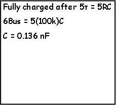
By using a function generator to generate a 1v step across a 100k resistor and the cable we measure the capacitance by measuring the time it takes for the capacitor to fully charge. Using that time we can calculate the capacitance value from the RC time constant. |

|
Fig 1.9 – Charge time of Coax cable capacitance |

|
Fig 1.10 – Multi-meter capacitance measurement |

|
Fig 1.8 – Coax cable used to find its capacitance |


|
Fig 1.11 – Vout of voltage divider with 1:1 probe/cable |

|
Fig 1.12 – Vout of voltage divider with 10:1 probe |
|
Using the 1:1 cable one cannot see the signal and only see a 500mV straight line. On the other hand with the compensated 10:1 scope probe one can see a small triangle wave that has a 500mV offset. This is happening because at that MHz frequency the capacitance in the coax cable affects the circuit because it acts like a short on the output. |
|
Discussion on PCB test points - When designing a PCB on can add an SMA connector to the board in order to have the ability to always connect a cable where you know the length from the board to your oscilloscope. Also when designing a PCB it is good practice to add a resistor next to your test point in order to ensure a 10:1 attenuation when measuring from that test point. |


|
Fig 1.6 – Oscilloscope Inputs |
|
The Measurement of the capacitance using the RC time constant is approximately the measurement from the multi-meter. |
|
The capacitance in the probe is too small causing the circuit not to charge quickly enough. |
|
The capacitance in the probe is too large causing the circuit to overshoot. |