Lab 2 - ECE 420L
Authored
by Stephanie Silic
silics@unlv.nevada.edu
February 5th, 2017
Lab Description
This lab details the reason for and operation of a compensated scope probe.
Lab Report
An oscilloscope probe has a variable capacitor which compensates for the capacitance of its cable and the capacitance of the BNC
connector on the scope. By adjusting this capacitor on the probe, we
can compensate for these capacitances. Below is the 10X, or 10:1, probe used in the lab:
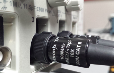
We
also notice in the photo shown above that the input resistance of the
oscilloscope is 1M Ohm and its input capacitance is 11.5 pF, as noted
in the gray lettering on the front of the scope, above the BNC
connectors.
- Show scope waveforms of a 10:1 probe undercompensated, overcompensated, and compensated correctly.
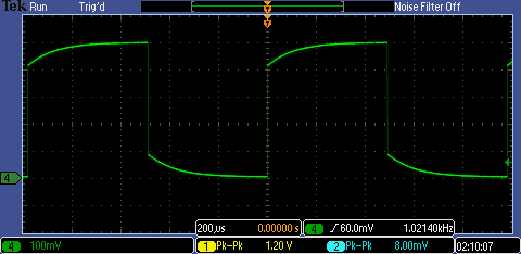
Undercompensated probe:

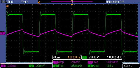
Overcompensated probe:
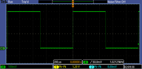
Properly compensated probe:
- Comment on where the type of scope probe (i.e. 1:1, 10:1, 100:1, etc.) is set on your scope.
The type of scope probe the oscilloscope accounts for is set by pushing
the color-coded channel button (I used the green channel 4) and
selecting "Probe Setup". This button will toggle between a 1X or 10X
setting, but it can also be set to a range of values from 1X to
1000 using the menu buttons to the right of the oscilloscope screen (not shown here).
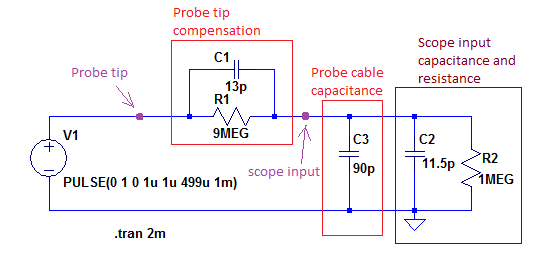
- Draft
the schematic of a 10:1 scope probe showing: the 9MEG resistor, 1 MEG
scope input resistance, capacitance of the cable, scope input
capacitance, and capacitance in the probe tip.
When
we probe the square wave at the point marked "Probe tip" we expect to
see the square wave at the scope input.
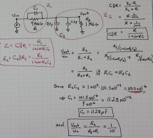
- Using circuit analysis,
and reasonable values for the capacitances, show using no
approximations that the voltage on the input of the scope is 0.1 the
voltage on the probe tip.
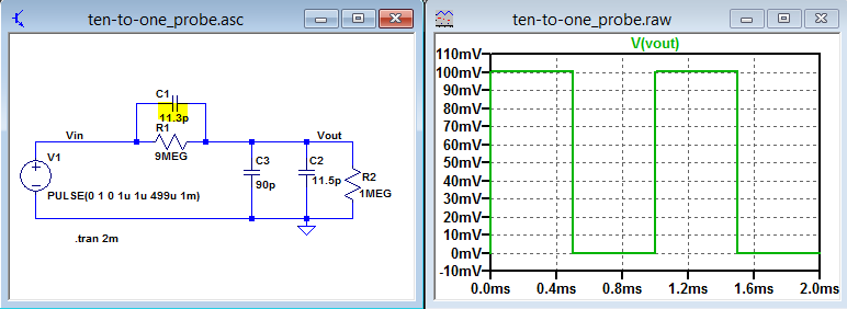
Simulating the circuit in LTSpice verifies what was calculated above:
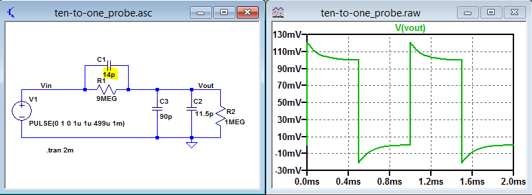
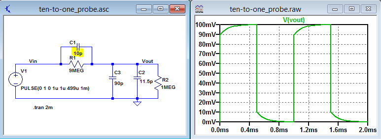
With the value of C1 set to 11.3pF, the output is a good square wave. We note that Vout is a pulse of 0 to 0.1V, which is 1/10th Vin as we expect with the 1:10 attenuation. If we simulate with a capacitor value greater than 11.3pF, we will get the overcompensated waveform seen at the beginning of the lab. If we use a capacitor value smaller than 11.3 pF, we will get the undercompensated waveform. These two situations are shown below:
Overcompensated:
Undercompensated
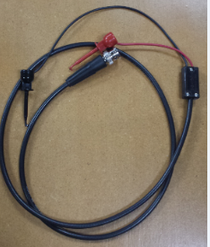
- Devise
an experiment, using a scope, pulse generator, and a resistor, to
measure the capacitance of a length of cable. Compare your measurement
results to the value you obtain with a capacitance meter. Make sure you
show your hand calculations.
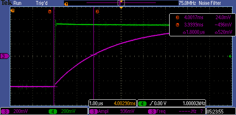
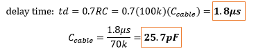
If we use the probe cable as the capacitor in an RC circuit, we can
read the delay time, or the time it takes the output to reach 50% of
the input and then calculate the capacitance using the formula for
delay time: td = 0.7RC.
Delay time measured on oscilloscope:
Hand Calculations:
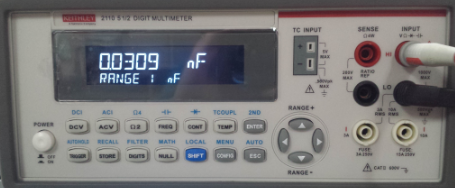
Measured capacitance value of cable used:
The cable was longer than 1 ft., and a typical capacitance for a
coaxial cable should be around 30pF per foot, so this value seems to be
low. Further experimentation and verification can be done to
confirm this value.
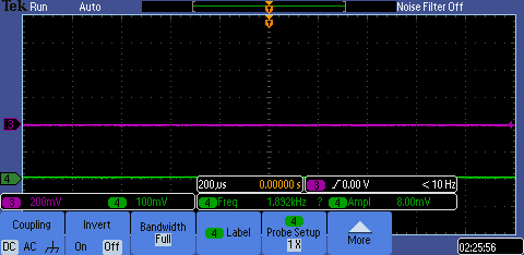
- Build
a voltage divider using two 100k resistors. Apply a 0 to 1 V pulse at
1MHz to the divider's input. Measure, and show in your report, the
output of the divider when probing with a cable (having a length
greater than or equal to 3 ft) and then a compensated scope probe.
Discuss and explain the differences.
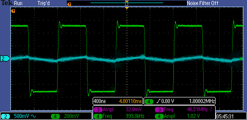
Measured with an uncompensated cable:
Measured with compensated 10X probe:
Using the uncompensated cable to measure the output of the voltage
divider at a 1MHz input square wave, the RC time constant of the
circuit is too large for the output to reach its full value in the
"on" time before the pulse goes low again. The output wave
seen above (top) versus the output wave above (bottom) illustrates the
difference in this charging time.
- Finally,
briefly discuss how you would implement a test point on a printed
circuit board so that a known length of cable could be connected
directly to the board and not load the circuitry on the board.
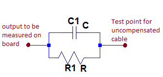
A
test point on a printed circuit board (PCB) can be implemeted by adding
a resisor and capacitor in parallel between the point on the board that
needs to be probed and where you will actually connect the cable.
Knowing the length of cable allows the correct capacitance value to be
chosen to compensate for the cable's capacitance. In this way, a cable
can be directly connected to the PCB. The value for the capacitor can be calculated in the same way as shown earlier in this lab.
- All work backed up by zipping the file and emailing to myself:

Return to my labs