Lab 5 - ECE 420L Engineering Electronics II Lab
Authored
by Frank Sanchez,
sanchezf@unlv.nevada.edu
3/08/2017
++++++++++++++
Experiment 1
++++++++++++++
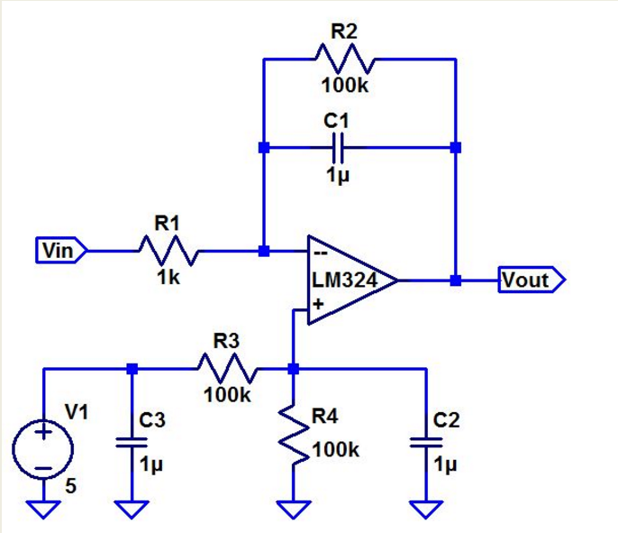
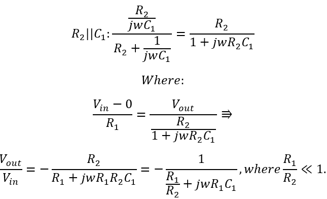
Calculate the frequency response of the following circuit. Ensure you show your clear hand calculations.
What can you neglect to simplify the calculation?
You can neglect the R1/R2 portion of the calculation do it haven't a very small affect to the calculation. R1/R2<<1..
Does the circuit work if you remove the 100k? Why or why not?
The 100k resistor is there in order to compensate the offset of the circuit. When removed, you'd get a DC offset; in hand you'd get an output saturation,
Does the 100k have much of an effect on the frequency response?
No
it doesn't, because the resistance is too large for the AC current to
flow through. The 100k doesn't have a big impact on the design.
Verify your calculations with experimental results.
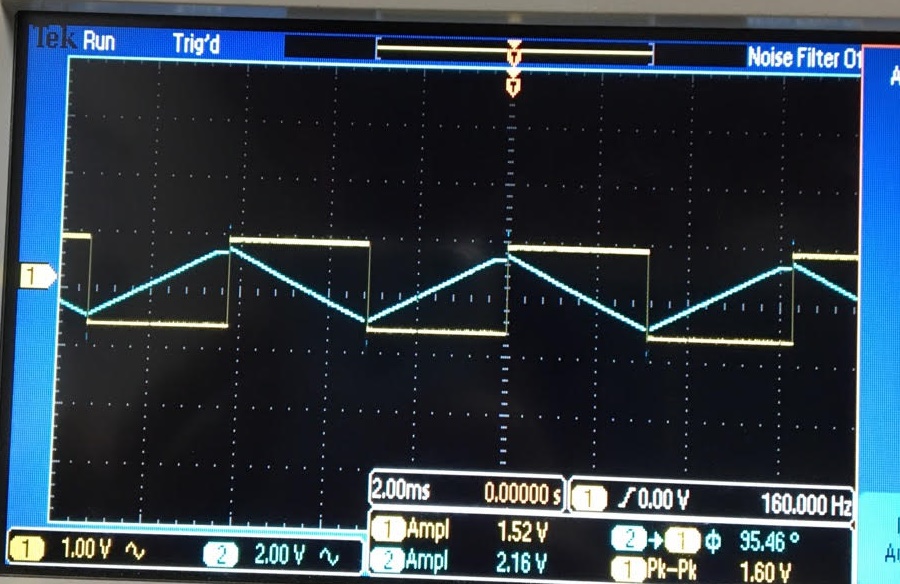
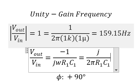
Show, at the unity-gain frequency of the integrator, that the input and the output have the same peak values.
The
experimental result displays the unity gain frequency for the circuit.
The image on the right is the calculated unity gain frequency and
theoretical phase angle.
Is the phase shift between the input and the output what you expect? Why or why not?Channel 1 displays around 3.2V pk-pk; while the output displays around 3V pk-pk.
The phase shift between both experimental and theoretical were on par with each other. As i got 90 degrees -theoretical, and 95 degrees-Experimental.
++++++++++++++
Experiment 2
++++++++++++++
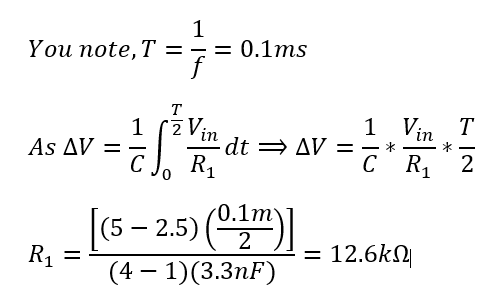
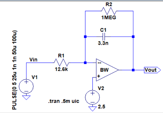
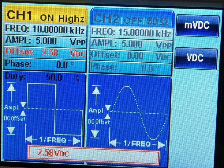
Next, design, simulate, and build a square-wave to triangle wave generation circuit.
- Assume the input/output frequency is 10 kHz and the output ramp must swing from 1 to 4 V centered around 2.5 V.
- Show all calculations and discuss the trade-offs (capacitor and resistor values, input peak, min, and average, etc.)
The
resistor and capictors were decided based upon what the lab had to
offer. In my case, I went for a 3.3nF capacitor. Shown below is how i
found my R1 resistor. A 1MEG resistor was used in the design in order
to compensate for any of the offset voltage.
Calculated Resistor:
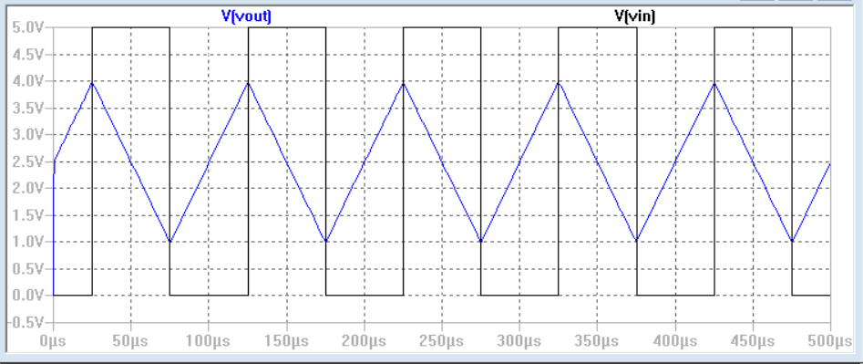
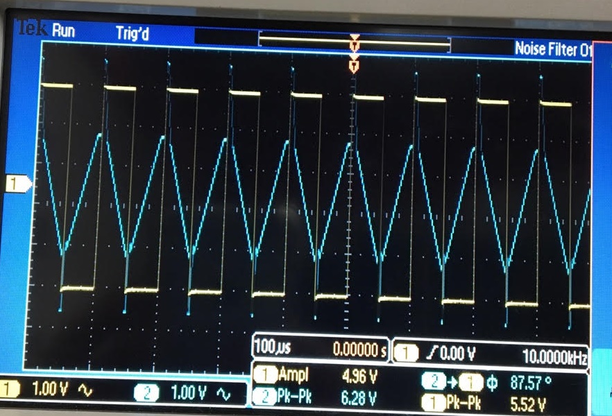
Experimental Result:
The input pulse is 5V pk-pk and the output swings from 1 to 4 volt at 10kHz.
++++++++++++++++++++++++++++++++++++++++++++++++++++++++++++++++++++++++++++++++
Lab Conclusion:
This
lab taught me how to systematically design a circuit that can comply
with an op amp; in hand, can create a square to triangle waveform. The
experiment provided the ability to see how the integrator circuit gives
a set output voltage proportional to the input voltage.
Return to EE 420L Labs