Lab 4 - ECE 420L Engineering Electronics II Lab
Authored
by Frank Sanchez,
sanchezf@unlv.nevada.edu
2/22/2017
++++++++++++++
Experiment 1
++++++++++++++
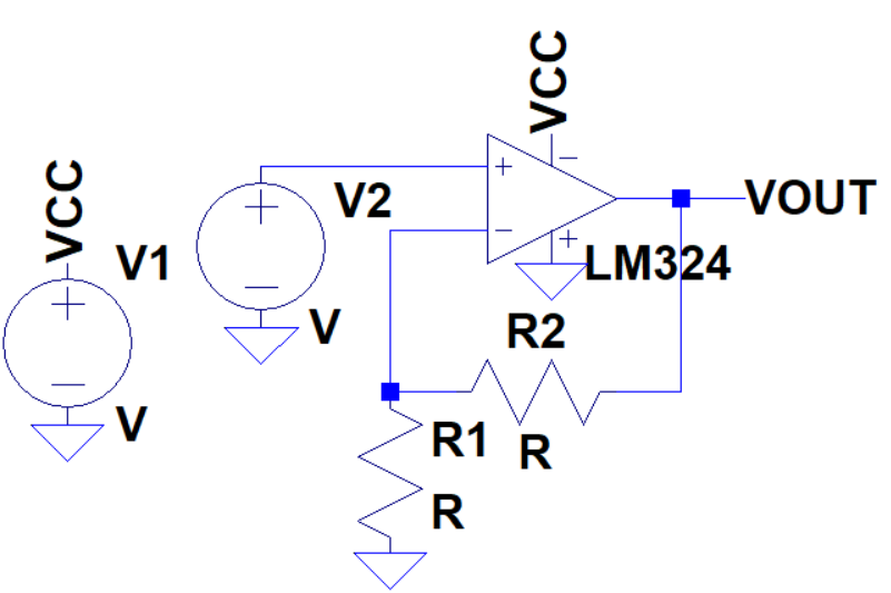
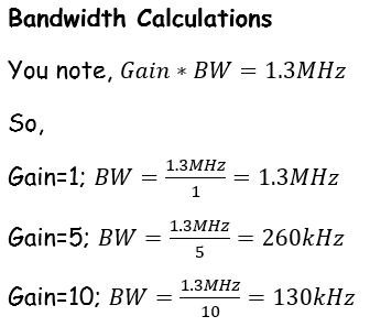
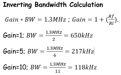
Estimate, using the datasheet, the bandwidths for non-inverting op-amp topologies having gains of 1, 5, and 10.
The datasheet indicates the unity gain frequency; which is 1.3MHz.

Calculations for Non-Inverting topology.
Experimentally
verify these estimates assuming a common-mode voltage of 2.5 V.
- Your
report should provide schematics of the topologies you are using for
experimental verification along with scope pictures/results.
- Associated comments should include reasons for any differences between your estimates and experimental results.
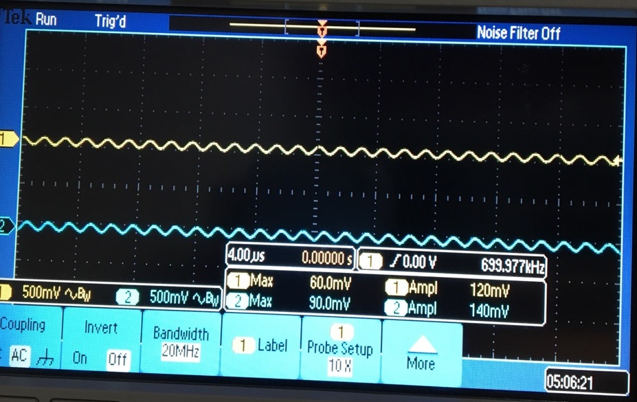
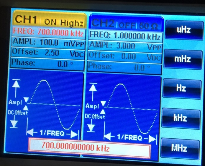
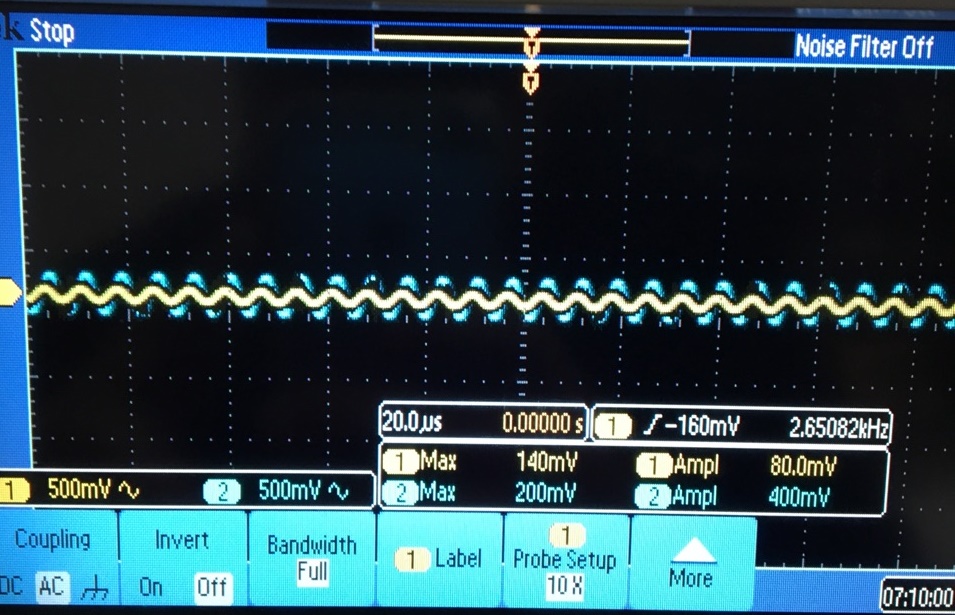
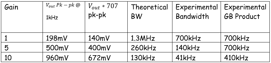
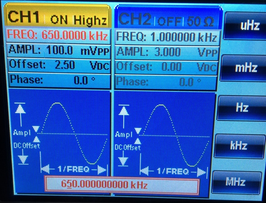
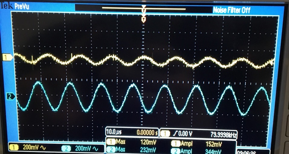
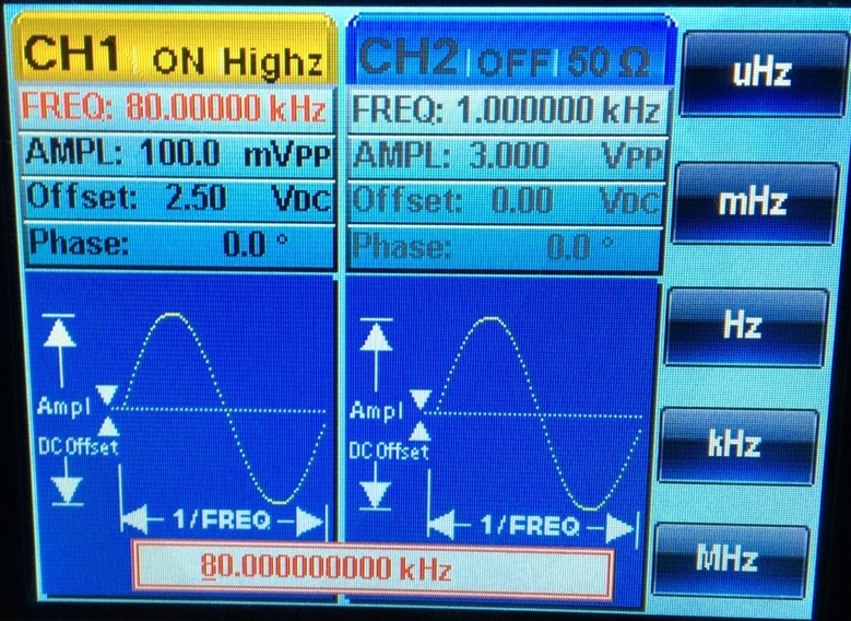
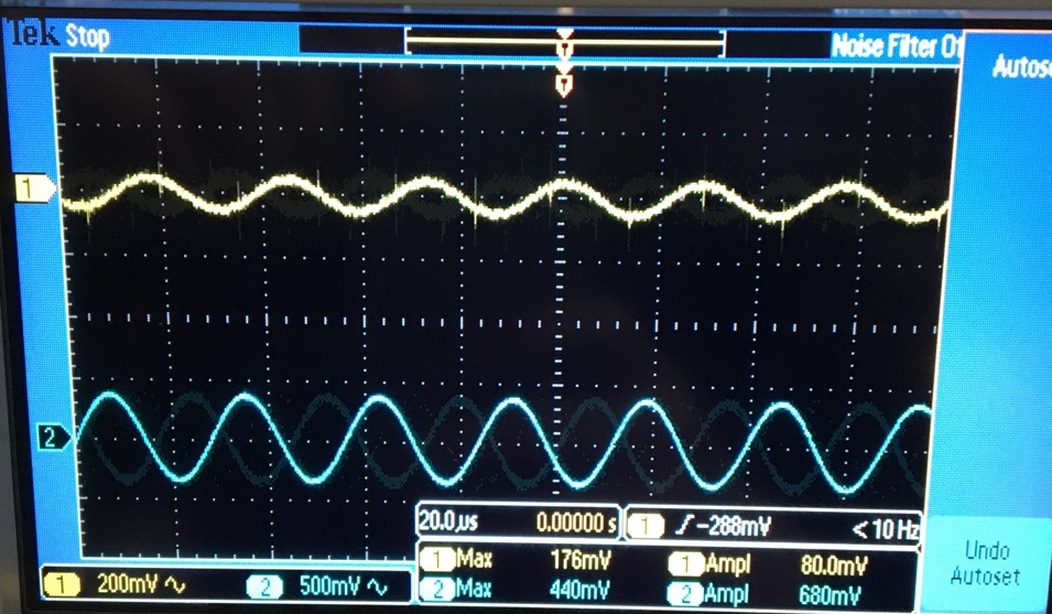
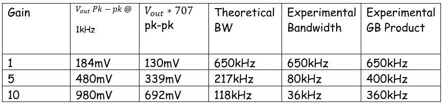
The
bandwidth is measured by first measing the gain for a non-inverting
cicuit by staring at a low frequency (1kHz). We find the bandwidth by
multiplying by .707*Vout. and changing the frequency until we reach the 3db bandwidth.
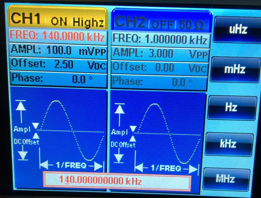
Gain of 1
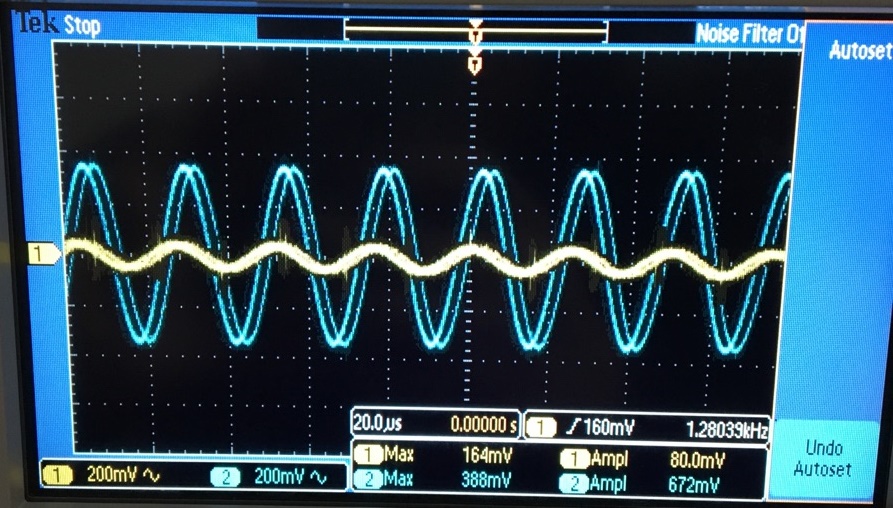
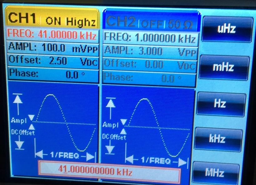
Gain of 5
Gain of 10
As
shown above, the theoretical values are higher than the experimental
values. The potential reason for such a high variation can be because
of the different test conditions applied to the op amp. Limiting the
Vcc to 5V in this experiment versus the test Vcc of 30V can make a big
difference. Other matters could have affected the outcome too, like the
temperature or possibly the test equipment being used.
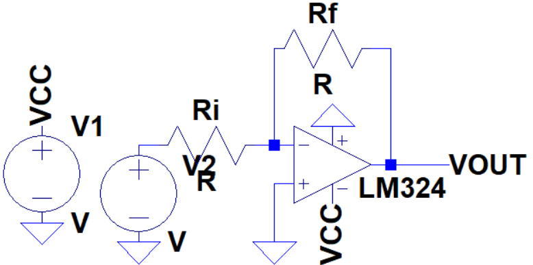
Repeat these steps using the inverting op-amp topology having gains of -1, -5, and -10.
Gain of 1
Gain of 5
Gain of 10Once
again, the experimental values are lower than the theoretical values.
This is probably because of the same situation discussed above.
++++++++++++++
Experiment 2
++++++++++++++
Design
two circuits for measuring the slew-rate of the LM324. One circuit
should use a pulse input while the other should use a sinewave input.Provide comments to support your design decisions.Comment on any differences between your measurements and the datasheet’s specifications.
A
non-inverting topology with a unity gain is used to measure the slew
rate. You note, slew rate is a measure of the change of the output
voltage over time. Measuring the rise time at 90% and 10% of the output
gave me a solution.
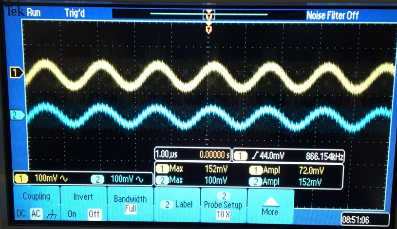
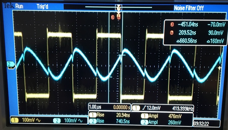
Sqare Input was performed:
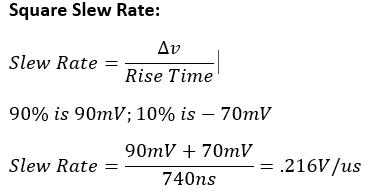
The
slew rate measured .216V/us vs. 0.4v/us on the datasheet. The
difference can be a variation that comes from using the parameter of 5V
for Vcc.
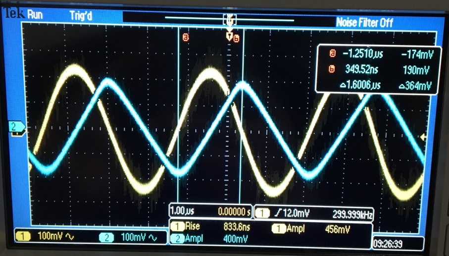
Sine Input was performed:
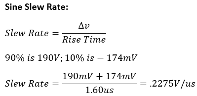
The
measured slew rate for the sine wave approximates the measured sine and
square values of 0.289V/us vs the datasheet's 0.4v/us. The difference
can be a variation that
comes from using the parameter of 5V for Vcc.
When finished backup your work.
Backed up work using OneDrive
++++++++++++++++++++++++++++++++++++++++++++++++++++++++++++++++++++++++++++++++
Lab Conclusion:
The
lab gave me the opportunity to understand how the GBP (Gain Bandwidth
Product) and Unity gain Frequency relate, and how to test a specific op
amp with certain conditions. This lab also gave me insight on how to
read a circuit datasheet properly.
Return to EE 420L Labs