Lab 2 - ECE 420L Engineering Electronics II Lab
Authored
by: Frank Sanchez,
sanchezf@unlv.nevada.edu
2/10/2017
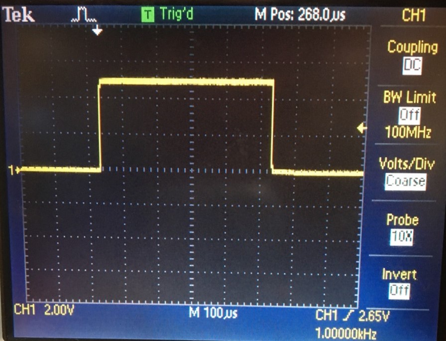
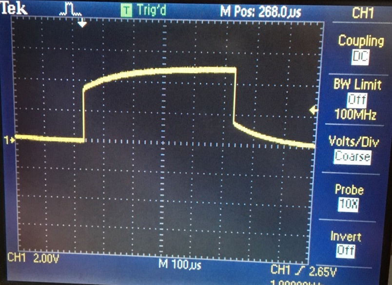
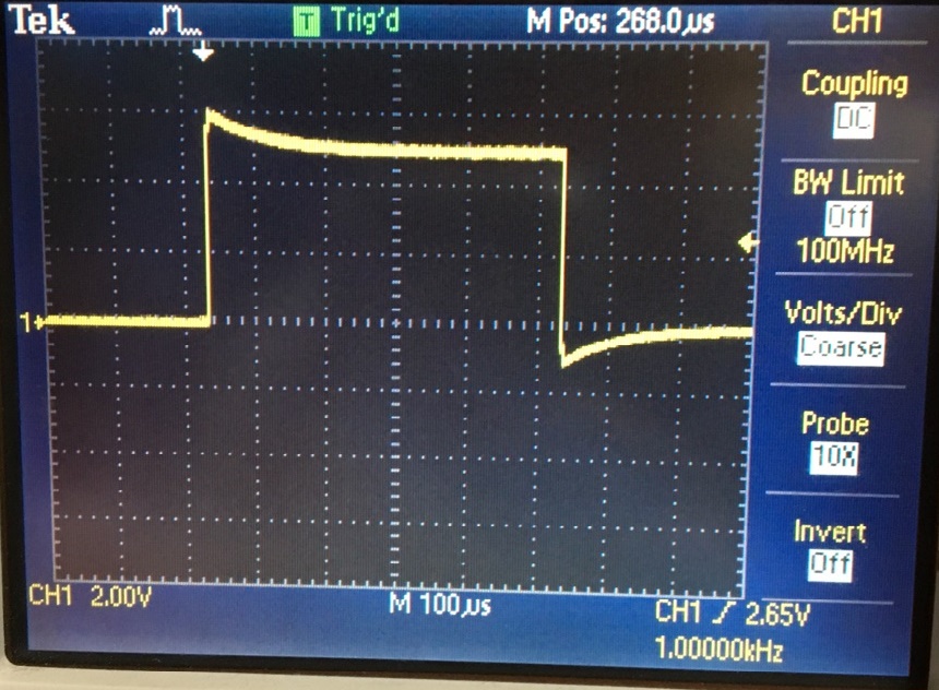
Experiment 1:Show scope waveforms of a 10:1 probe undercompensated, overcompensated, and compensated correctly.
Compensated
OverCompensated
UnderCompensated
Experiment 2: Comment
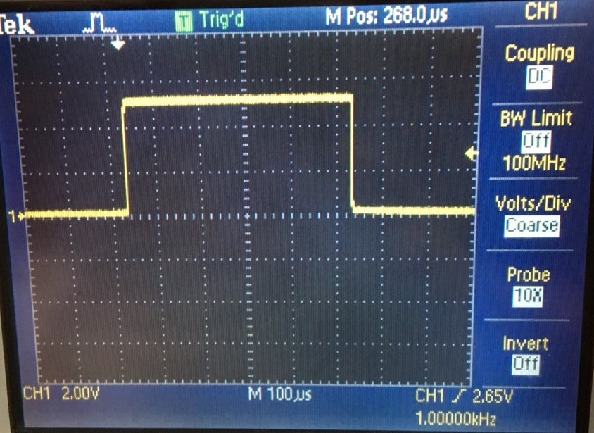
on where the type of scope probe (i.e., 1:1, 10:1, 100:1, etc.) is set
on your scope (some scopes detect the type of probe used automatically).
1:1 Scope
Probe
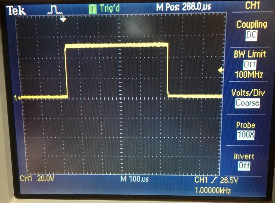
10:1 Scope Probe
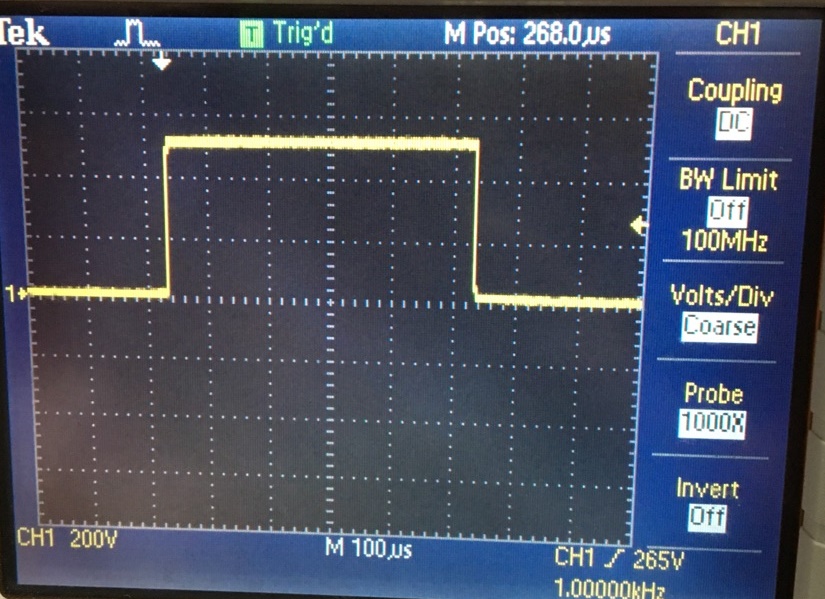
100:1 Scope Probe
1000:1 Scope Probe
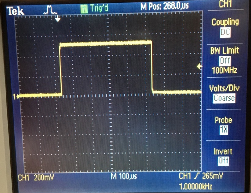
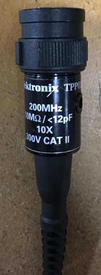
The
pictures above show the of probe used for the experiment. The channel
menu on the oscilloscope allows the user to properly attenuate a
probe from 1x to 1000x. Other parameters in regards to the BNC
connector inclued its input resistance of 10M-ohms, 12pF input
capacitance, and a bandwidth of 100MHz.
- Draft
the schematic of a 10:1 scope probe showing: the 9 MEG resistor, 1 MEG
scope input resistance, capacitance of the cable, scope input
capacitance, and capacitance in the probe tip.
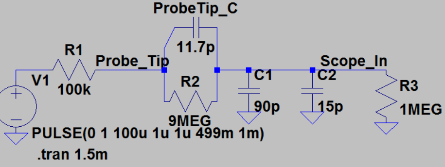
The
circuit above is a representation of a circuit taught to the student
during the pre-lab. This circuit represents a probe attenuation of 10x
to 1x ratio.
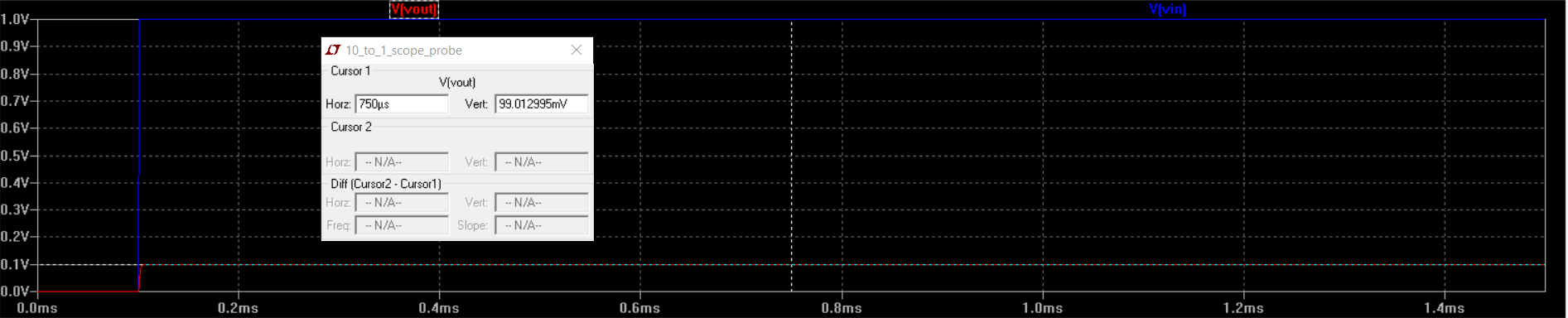
Running a simulation for this circuits proves
that its a clear representation of a probe and its parameter
effects and how its can output 1V from a 100mV input.
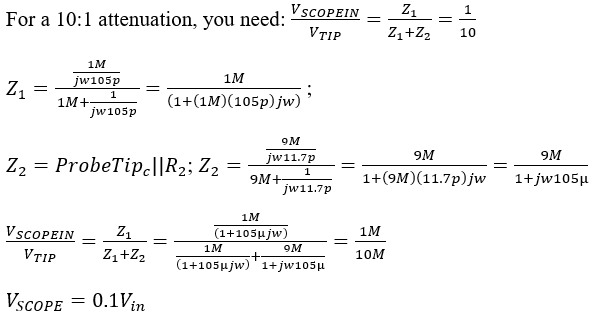
- Using
circuit analysis, and reasonable/correct values for the capacitances,
show using circuit analysis and alegbra (no approximations), that the
voltage on the input of the scope is 0.1 the voltage on the probe tip.
- Devise
an experiment, using a scope, pulse generator, and a resistor, to
measure the capacitance of a length of cable. Compare your measurement
results to the value you obtain with a capacitance meter. Make sure you
show your hand calculations.
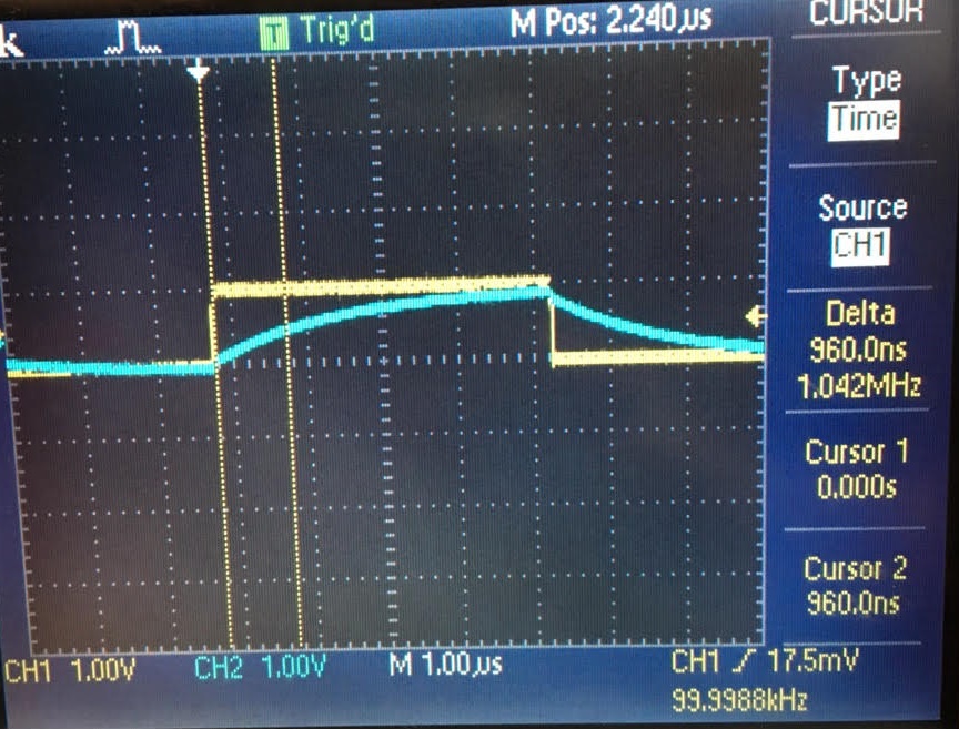
In order to measure the capacitance of the cable; you can create an RC circuit using the scope probe and resistor of 108.5kΩ.
By the use of a voltage pulse as an input; one can measure the
time the circuit takes to reach around 50% of voltage pulse, know
as time delay. My experimental result ended up being a time delay of
960ns. for a 1 volt input pulse. This in hand gave me a
calculated value of close to 13pF.
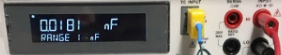
Measuring the cable capacitance
with a multimeter, gave a result of about 18.1pF. But by subtracting
the capacitance of the multimeter, you'd get around 11.1pF which is
close to the calculated capacitance value.
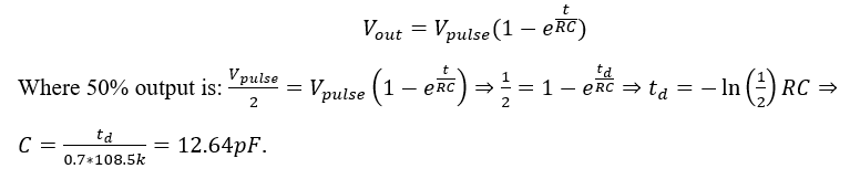
- Build
a voltage divider using two 100k resistors. Apply a 0 to 1 V pulse at 1
MHz to the divider's input. Measure, and show in your report, the
output of the divider when probing with a cable (having a length
greater than or equal to 3 ft) and then a compensated scope probe.
Discuss and explain the differences.
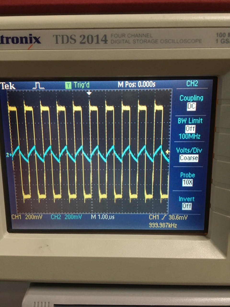
The
result on the left shows a compensated output to the input which has a
10:1 attenuation which has a capacitance that is being introduced
to it. The result on the left shows an uncompensated output, that helms
a big capacitor that is taking a while to charge. - Finally,
briefly discuss how you would implement a test point on a printed
circuit board so that a known length of cable could be connected
directly to the board and not load the circuitry on the board.
In
order to implement a test point on a pcb so that a known length of
cable can be connected directly to the board, is by placing acapacitor
and a resistor in parallel. This is done in order to prevent any
effects from the cable connected to the pcb to occur.
++++++++++++++++++++++++++++++++++++++++++++++++++++++++++++++++++++++++++++++++
Conclusion:
Lab
2 gave us an idea on how a compensated or uncompensated scope probe can
affect a circuit. If it being an uncompensated scope probe which
introduces a big capacitance or having a compensated circuit which
compensates for the input capacitance and cable cap. This lab gives us
an understanding on what might affect a circuit while using a measuring
device.
Return to EE 420L Labs