Lab4 - EE 420L
Authored
by Allan Pineda
pineda3@unlv.nevada.edu
February 22, 2017
Lab Description: Op-amps II, gain-bandwidth product and slewing
This lab will utilize the LM324 op-amp (LM324.pdf).
This
lab is about understanding the operation of op-amps in regards to
its gain-bandwidth products and slew rate as well as the effect of
a high requency in the circuits.
For the following questions and experiments assume VCC+ = +5V and VCC- = 0V.
- Estimate, using the datasheet, the bandwidths for non-inverting op-amp topologies having gains of 1, 5, and 10.
Answer:
Below is a data sheet of LM324 and Hand Calculation showing on how to
estimate the Gain Bandwidth of an op-amp. See Figure 1
Figure 1:

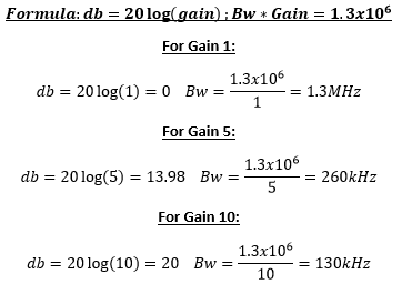

The data sheet above is the graph for LM324. It is a plot for frequency
in hertz vs gain in dB. Using 1V/V gain, the corresponding value
in dB is found to be 0 dB voltage gain and by viewing this gain with respect to
frequency, this is approximately around 1.3MHz. For the 5V/V gain the
corresponding value is around 13.9 dB and the bandwidth is 260kHz.
Moreover, for the non-inverting gain of 10V/V which is 20dB,
the bandwidth is frequency is 130kHz.
- Experimentally verify these estimates assuming a common-mode voltage of 2.5 V.
For this experiment, a non-inverting op-amp topology was used with a
VCM of 2.5V constructed from previous lab experiment. Figure 2 are the verifying results.
Figure 2: Non_Inverting Op-Amp Circuit
Non
Inverting Op-Amp Circuit:


Below is the gain of 1 for non-inverting op-amp. It shows that the actual frequency is around 900kHz.


Gain 1 Frequency and Sinewave
Below is the gain of 5 for non-inverting op-amp. It shows that the actual frequency is around 130kHz.


Gain 5
Frequency and Sinewave
Below is the gain of 10 for non-inverting op-amp. It shows that the actual frequency is around 46kHz.


Gain 10 Frequency and Sinewave
The goal for
this lab is to find the bandwidth of a non-inverting op-amp with
different gain (i.e 1 ,5, and 10) and compare the experimental results
in a data sheet LM324. In order to find the bandwidth for each gain, one need
to set the frequency at low level to get maximum output voltage.
Then the maximum voltage need to be multiply by 0.707 to be at the
roll-off frequency (i.e 3 dB). By varying the frequency until it reach
the resulting product of 0.707*maximum voltage, one can get the
bandwidth for a certain gain being tested. For example at Gain of 5,
(See Figure Gain 5 above) the frequency was set to a low level at 1kHz
to get the maximum voltage which is 472mV, then it get multiplied by
0.707 which resulted in 330mV. On the scope wave and function
generator, by varying the frequency, the voltage in the scope
changing with respect to frequency. Once the voltage reach the 330mV,
the frequency at function generator, which is 130kHz is the resulting
bandwidth at gain of 5. Notice the results in experiment is different
compare to the data sheet. This is because the supply voltage was use
in the lab experiment is only 5V while on the data sheet was 30V.
If 30V was used in the lab, the experimentals result will be close to the
value on the data sheet. For the gain of 1 and gain of 10, the process
is the same and the higher the gain being tested the further the result will be.
- Repeat these steps using the inverting op-amp topology having gains of -1, -5, and -10.
For this experiment, a inverting op-amp topology was used with a
VCM of 2.5V. Figure 3 are the result in verifying the result.
Figure 3
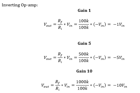
Inverting Op-Amp Circuit

Below is the gain of 1 for Inverting op-amp. It shows that the actual frequency is around 640kHz.


Gain 1 Frequency and Sinewave
Below is the gain of 5 for Inverting op-amp. It shows that the actual frequency is around 115kHz.


Gain 5
Frequency and Sinewave
Below is the gain of 10 for Inverting op-amp. It shows that the actual frequency is around 39kHz.

Gain 5
Frequency and Sinewave
Explanations:
For this experiment, an inverting topology was used. The calculation
of bandwidth will be different compare to non-inverting topology.
However, one can find the bandwidth of inverting op-amp by using
the non-inverting formula for bandwidth. The resulting formula
is |1+(Rf/Ri)|*BW=1MHz. To calculate for the unity gain, the Rf
and Ri must have the same value so that gain of 1 then |1+1|*BW=1MHz
will be BW = 500kHz. Notice that this bandwidth is only haft of the
non-inverting topology. Also, increasing the gain bandwidth will result
in higher frequency. From the figure above, notice that the gain of 1
is about 640kHz only. This is just almost haft of the frequency of
non-inverting topology. This can be obtain by decreasing the frequency
to 1kHz to get the output reference voltage and multiplying the result
by 0.707 to get the output voltage of -141mV. For a gain of 5 the final
output voltage is 264mV correspond to 115kHz frequency.
Finally, gain of 10, the same process were taken to get the value
of output voltage 664mV and frequency 39kHz shown in the figure 3 above.
Since the voltage Vcc used in this lab experiment is alot smaller
than the data sheet, the values obtain are quite different. In
contrast, if the voltage input (Vcc) is the same, the result will be
the same if not the difference is really small.
- Design
two circuits for measuring the slew-rate of the LM324. One circuit
should use a pulse input while the other should use a sinewave input.
- Provide comments to support your design decisions.
- Comment on any differences between your measurements and the datasheet’s specifications.
Figure 4
Below is the Square Wave slew rate for Inverting op-amp. It shows that the actual frequency is around 30kHz.

Below is the Sine Wave slew rate for Inverting op-amp. It shows that the actual frequency is around 300kHz.

Explanations:
The last experiment is finding the
slew rate of the designed circuit from an input sine wave and square wave. To
find the slew rate of the circuit, one must know the definition of slew rate.
Slew rate is the maximum rate at which the op-amp reacts to a sudden change of
input. Measurements in figure 4 are done by taking the derivative of the initial
voltage and sine frequency with respect to time. Notice
increasing initial voltage or the frequency will result in increase of slew and
decreasing either initial voltage or frequency will decrease the slew rate as
well.
An inverting op-amp circuit was
used in this part of the experiment to find the slew rate for both sine wave
and square wave. Changing the feature of the function generator into sine wave,
and adjusting the frequency into 300kHz will allow the user to measure the slew
rate in the scope. The resulting value is 440mV at 1.68micro sec, thus the slew rate is 261.9mV/microsec. On the other
hand, when changing the function generator into square wave, one must change
the frequency to 30kHz to measure the slew rate. Doing so will get 452mV at
1.54micro sec, thus, the slewrate is 293.5mV/microsec. Note that this values are obtain by measuring the rise time at
90% and 10% value of the output signal. The date sheet of LM324 the slew rate is
0.4V, which is really close to the experiment result.