Lab2 - EE 420L
Authored
by Allan Pineda
pineda3@unlv.nevada.edu
February 10, 2017
Lab Description: Operation of Compensated Probe
- Show scope waveforms of a 10:1 probe undercompensated, overcompensated, and compensated correctly.
- Comment
on where the type of scope probe (i.e., 1:1, 10:1, 100:1, etc.) is set
on your scope (some scopes detect the type of probe used automatically).
- Draft
the schematic of a 10:1 scope probe showing: the 9 MEG resistor, 1 MEG
scope input resistance, capacitance of the cable, scope input
capacitance, and capacitance in the probe tip.
- Using
circuit analysis, and reasonable/correct values for the capacitances,
show using circuit analysis and alegbra (no approximations), that the
voltage on the input of the scope is 0.1 the voltage on the probe tip.
- Devise
an experiment, using a scope, pulse generator, and a resistor, to
measure the capacitance of a length of cable. Compare your measurement
results to the value you obtain with a capacitance meter. Make sure you
show your hand calculations.
- Build
a voltage divider using two 100k resistors. Apply a 0 to 1 V pulse at 1
MHz to the divider's input. Measure, and show in your report, the
output of the divider when probing with a cable (having a length
greater than or equal to 3 ft) and then a compensated scope probe.
Discuss and explain the differences.
- Finally,
briefly discuss how you would implement a test point on a printed
circuit board so that a known length of cable could be connected
directly to the board and not load the circuitry on the board.
Experiment_1:
- Show scope waveforms of a 10:1 probe undercompensated, overcompensated, and compensated correctly.
Compensated Correctly

UnderCompensated

OverCompensated

Experiment_2:
- Comment
on where the type of scope probe (i.e., 1:1, 10:1, 100:1, etc.) is set
on your scope (some scopes detect the type of probe used automatically).


The
image above shows the type of probe used in the lab experiment. The
details about the cable is labeled and found in the input of the cable.
The 10X attenuation indicates that the probe is a 10:1 probe.
Other parameter can also be found such as input resistance of 10MΩ,
200MHz frequency and input capacitance 12pF. The channel menu in the
oscilloscope allows the user to change the proper attenuation ranging
from 1X up to 1000X. By changing the attenuation the voltage reading in the scope is also changing depend on the set X.
Experiment_3:
- Draft
the schematic of a 10:1 scope probe showing: the 9 MEG resistor, 1 MEG
scope input resistance, capacitance of the cable, scope input
capacitance, and capacitance in the probe tip.
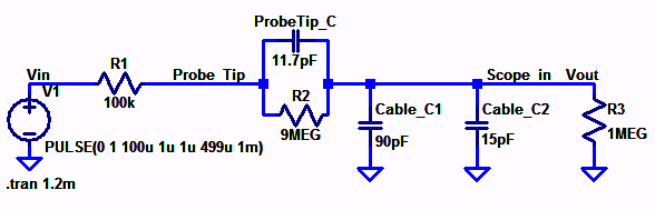

The
schematic circuit above represent the circuits probe that was presented
in the pre-lab video. Running the simulation using LTspice will give us
a ratio of 1000mV input and 100mV output which indicates a 10:1 ratio.
Thus the probe ratio has been verified.
Experiment_4:
- Using
circuit analysis, and reasonable/correct values for the capacitances,
show using circuit analysis and alegbra (no approximations), that the
voltage on the input of the scope is 0.1 the voltage on the probe tip.

Experiment_5:
- Devise
an experiment, using a scope, pulse generator, and a resistor, to
measure the capacitance of a length of cable. Compare your measurement
results to the value you obtain with a capacitance meter. Make sure you
show your hand calculations.


Hand Calculation: for 50% Reach Output

To measure the cable capacitance, one must create an RC circuit using the cable probe and a resistance value of 108.5kΩ
connected in series. Using a voltage pulse as an input and measuring
the time delay for the output to reach the 50% of voltage
pulse, we can obtain the value of the capacitance by deriving the
formula from above. The image above shows that the capacitance is
approximately 11.1pF by subtracting the value from the multi meter (i.e
0.0181nF-0.007nF). Comparing the value obtain from hand calculation,
the value are slightly off because of some other parameters involve
during the experiment. However, we can conclude that the two are
comparatively close.
Experiment_6:
- Build
a voltage divider using two 100k resistors. Apply a 0 to 1 V pulse at 1
MHz to the divider's input. Measure, and show in your report, the
output of the divider when probing with a cable (having a length
greater than or equal to 3 ft) and then a compensated scope probe.
Discuss and explain the differences.


The
reading from the left is when the probe is compensated. It is measures
by taking the input and output voltage of the divider. It has an
attenuation probe of 10:1, which mean there is a result of 100mV
output per 1V of input. This is due to the introduced capacitance
in the circuits that compensate the capacitance from the scope which
help the capacitor take time to charge up resulting in a measurable
signal. On the other hand, the reading from the right is when the probe
is uncompensated. The introduce capacitance in this manner is large
that makes the reading almost linear due to the extended time necessary
for the capacitance to fully charge. It makes the cable to act like a
wire.
Experiment_7:
- Finally,
briefly discuss how you would implement a test point on a printed
circuit board so that a known length of cable could be connected
directly to the board and not load the circuitry on the board.
We
can implement a test point on a PCB by including a resisitor and a
variable capacitor connected in parallel to prevent the unnecessary
effects that may occur when a known length of cable is attached to the
test point. By having this in the circuitry board, we have the ability
to adjust the capacitor to make the compensated probe into
uncompensated cable to minimized the effect of the scope input
capacitance.
Conclusion:
The
experiment is about learning on how to compensate and uncompensate
probe as well as the technique used in probing. It is very important to
know the theory behind these method because it can have a significant
effects in designing a circuits. Having the ability to understand the
effect of this method, can help reduce the unnecessary results and
allow for a faster signals in designing a circuits.