Lab 5 - ECE 420L
Authored
by Desi Battle,
March 7th, 2017
- Calculate the frequency response of the following circuit. Ensure you show your clear hand calculations.

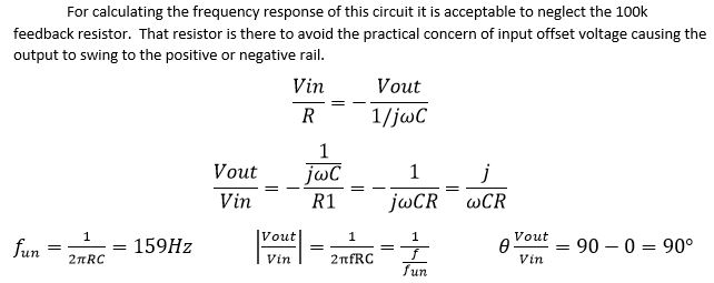
- Verify your calculations with experimental results.
- Show, at the unity-gain frequency of the integrator, that the input and the output have the same peak values.
- Is the phase shift between the input and the output what you expect? Why or why not?
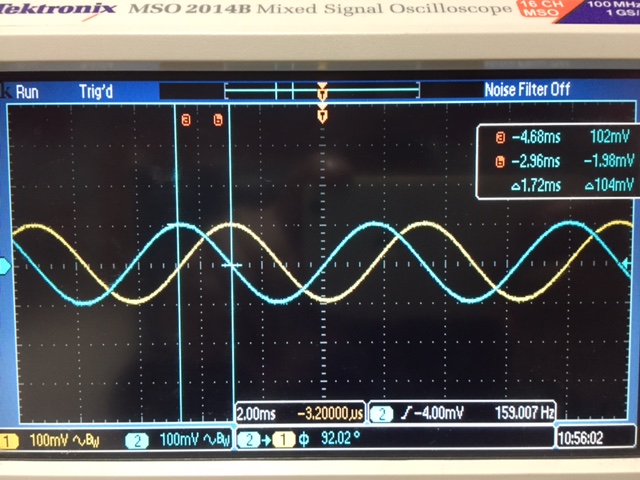
Oscilloscope photo verifying 90 degree phase shift and unity gain at 159 Hz.
I did expect the results to match my hand calculations.
Design, simulate, and build a square-wave to triangle wave generation circuit.
Assume the input/output frequency is 10 kHz and the output ramp must swing from 1 to 4 V centered around 2.5 V.
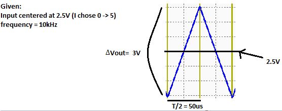
Sketch of triangle wave we are attempting to create
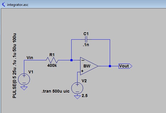
Schematic for specified triangle wave
Choosing R and C
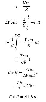
As shown in the schematic above, eventually I settled with C = 0.1n and R = 400k
I found in my experiments that minimizing C and maximizing R produced the best results.
It is unclear to me why different combinations of R and C = RC produced different results, but I believe
this is due to the components varying from the values they were designed to have.
I chose a Pulse from 0 to 5 V because it was the simplest way for me to meet the requirements of centering at 2.5 V
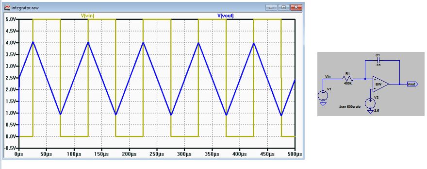
Simulation results of Schematic
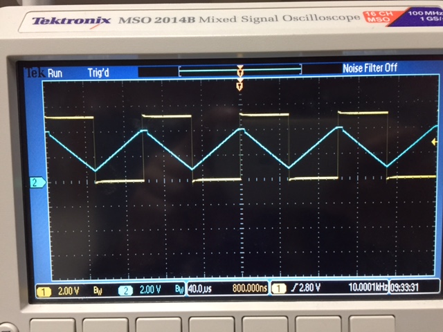
Oscilloscope photo verifying hand calculations above
return