EE 420L Engineering Electronics II - Lab 4
3/2/16
Lab 4: Op-amps II,
gain-bandwidth product and slewing
Watch
the video op_amps_II,
review op_amps_II.pdf (associated notes), and simulate the
circuits in op_amps_II.zip.
Again, this lab will utilize the
LM324 op-amp (LM324.pdf).
For the following questions and
experiments assume VCC+ = +5V and VCC- = 0V.
Experiment
1:
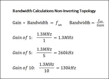
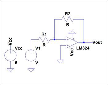
Estimate, using
the datasheet, the bandwidths for non-inverting op-amp topologies having gains of
1, 5, and 10.
The
datasheet indicates the unity gain frequency, ![]() , is 1.3MHz. The calculations will be listed below for the
non-inverting topology. The figure to the left is the schematic for a
non-inverting topology.
, is 1.3MHz. The calculations will be listed below for the
non-inverting topology. The figure to the left is the schematic for a
non-inverting topology.
![]()
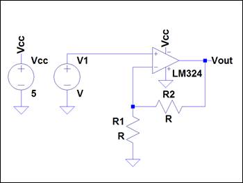
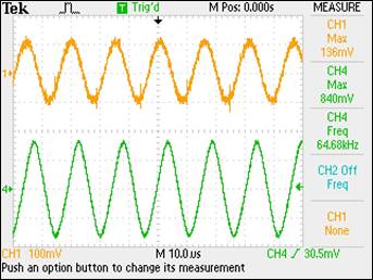
Experimentally verify these estimates
assuming a common-mode voltage of 2.5 V.
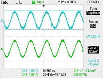
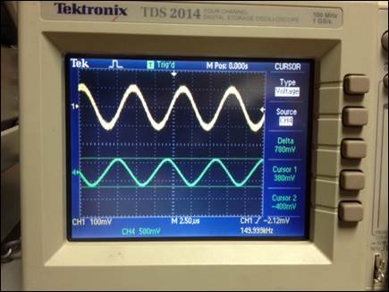
The
bandwidth is measured by first measuring each gain for the topology starting at
1kHz. Next, we find the bandwidth by multiplying ![]() and changing the frequency
until we reach the resulting 3dB bandwidth. The experimental versus theoretical
values are included in the table following the waveforms and/or pictures. This
laboratory experiment includes images of captured waveforms and pictures of
waveforms for different parts of the laboratory. This is due to equipment
availability at the time each experiment was conducted, ie
multiple oscilloscopes in the laboratory do not include an option for USB
screen-captures.
and changing the frequency
until we reach the resulting 3dB bandwidth. The experimental versus theoretical
values are included in the table following the waveforms and/or pictures. This
laboratory experiment includes images of captured waveforms and pictures of
waveforms for different parts of the laboratory. This is due to equipment
availability at the time each experiment was conducted, ie
multiple oscilloscopes in the laboratory do not include an option for USB
screen-captures.
Gain of 1
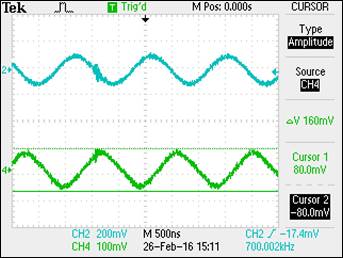
Gain of 5

Gain of 10
|
Gain |
|
|
Experimental Bandwidth |
Theoretical Bandwidth |
Experimental GB Product |
|
1 |
232mV |
164mV |
700kHz |
1.30MHz |
700kHz |
|
5 |
1.28V |
905mV |
125kHz |
260kHz |
625kHz |
|
10 |
1.24V |
877mV |
65kHz |
130kHz |
650kHz |
Clearly,
the theoretical values are significantly higher than the experimental values.
The experimental GB Product suggests a value of approximately 700kHz versus 1.3MHz on the datasheet. Potential reasons for
variations in these values can possibly be attributed to the differences in the
test conditions used when the GBP was calculated for the datasheet. Limiting Vcc to 5V in this experiment versus a test Vcc of 30V is one substantial variation that can explain
the differences, as well as variations in temperature, equipment calibration
and/or experimental errors.
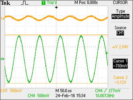
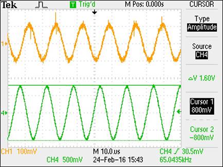
Repeat these steps using the
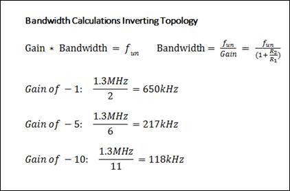
inverting op-amp topology having gains of -1, -5, and -10.
The
figure to the left is the schematic for an inverting topology. The calculations
for the bandwidth are displayed in the image to the right.
Repeating
the same process for the inverting topology as performed for the non-inverting
topology leads to the following results.
Gain of -1
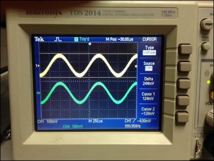
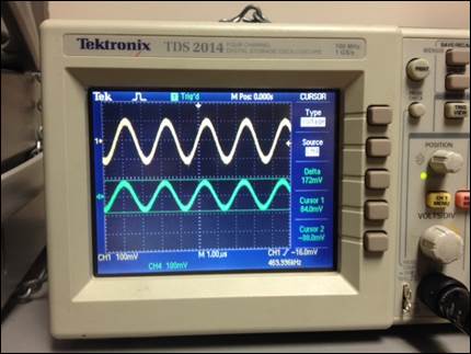
Gain of -5
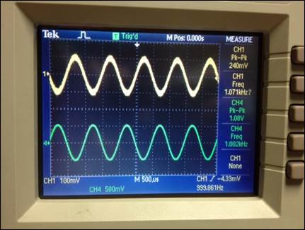
Gain of -10
|
Gain |
|
|
Experimental Bandwidth |
Theoretical Bandwidth |
Experimental GB Product |
|
1 |
244mV |
173mV |
470kHz |
650kHz |
470kHz |
|
5 |
1.08V |
763mV |
150kHz |
217kHz |
750kHz |
|
10 |
2.34V |
1.65V |
65kHz |
118kHz |
650kHz |
The
inverting topology produced similar results to the non-inverting topology
relative to the experimentally determined versus theoretically calculated
values. Once again, the experimental values are significantly lower than the
theoretical values. This may be attributed to the same variations discussed
above.
Experiment
2
Design two circuits for measuring the
slew-rate of the LM324. One circuit should use a pulse input while the other
should use a sinewave input.
The
LM324 datasheet lists the slew rate at ![]() .
.

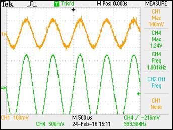
A
simple non-inverting topology with a unity gain was used to experimentally
measure the slew rate. Since slew rate is a measure of the rate of change of
the output voltage over time, using this circuit presented an efficient method
of measurement. Measuring the rise time
at 10% and 90% of the output allowed for a simple calculation. The first
measurement was performed using a pulse input, as detailed below.
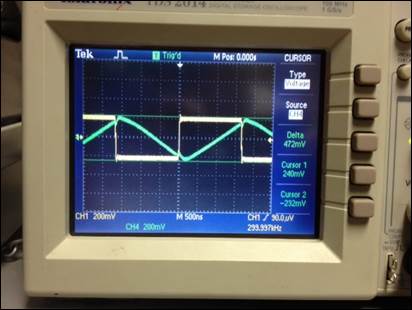
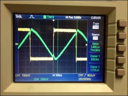
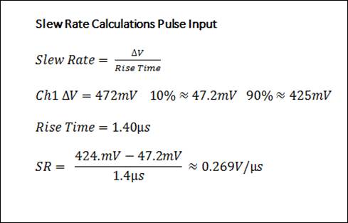
As
seen in the calculations above, the slew rate determined via the pulse input
measures ![]() versus the
datasheet estimate at
versus the
datasheet estimate at ![]() . The
differences in theoretical and experimental values may be attributable to
variances in the 5V used for this experiment versus the voltage and conditions used
to estimate the slew rate by the manufacturer.
. The
differences in theoretical and experimental values may be attributable to
variances in the 5V used for this experiment versus the voltage and conditions used
to estimate the slew rate by the manufacturer.
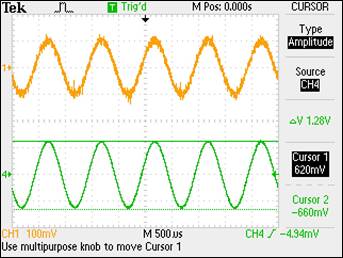
The same
circuit was used to measure the slew rate for the sine input with the results
discussed below.
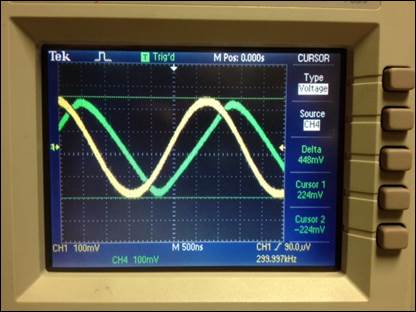
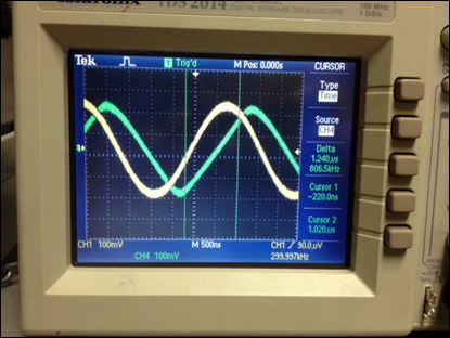
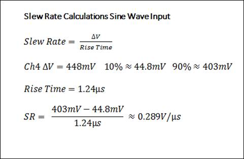
The
measured slew rate for the sine wave approximates the value measured for the
pulse input, ![]() with an experimental value of
with an experimental value of ![]() versus the
datasheet estimate of
versus the
datasheet estimate of ![]() . Differences
between the two values may be attributable to the same variances discussed
above for the pulse input.
. Differences
between the two values may be attributable to the same variances discussed
above for the pulse input.
Conclusion
Laboratory
experiment four offered practical comparisons of the LM-324's gain-bandwidth
product and slew rate as specified by the manufacturer versus experimentally
determined values. The experimental values obtained via the given parameters in
this laboratory resulted in substantial variations between experimental values,
manufacturer test values, and theoretically calculated values. However, given
the opportunity to test under conditions similar to the manufacturers test
conditions, such as the same voltage, room temperature and laboratory
equipment, could potentially result in values similar to those claimed on the
datasheet. Lastly, the laboratory exercise presented an opportunity to explore
the relationship between the gain-bandwidth product and the unity gain
frequency.
Return to
Monahan Lab Report Directory
Return
to EE 420L Spring 2016 Student Directory